Table of Contents
What is Electrospinning?
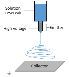
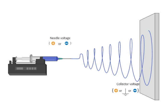
Electrospinning is a voltage-driven, fabrication process governed by a specific electrohydrodynamic phenomenon where small fibers are yielded from a polymer solution. The most basic setup for this technique involves a solution contained in a reservoir — typically a syringe — tipped with a blunt needle (at least for needle-based electrospinning), a pump, a high voltage power source, and a collector.
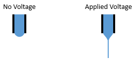
The spinning process begins when an electric field is established between the needle tip and collector by applying a specified voltage. While the pump causes the solution to flow at a constant rate, charges accumulate at the surface of the liquid. Soon a point is reached where the electrostatic repulsion is larger than the surface tension that results in the liquid meniscus deforming into a conically shaped structured known as a Taylor cone. This can be clearly seen in the video below as the flow changes from dripping to a charged cone-shaped structure on the tip of the needle.
Once the Taylor cone forms, the charged liquid jet ejects towards the collector. Collectors differ by their geometrical configurations that come in many forms: flat plates, rotating drums, mandrels, and disks, but these are not the only variations.
If the solution viscosity is within a certain threshold, the technique generates solid fibers as the solvent evaporates. Violent whipping motion occurs between the cone and the collector, resulting in a non-woven fiber mat deposited on the collector.
Introduction to the Electrospinning Process
Electrospinning finds use in several industries: life science, biotextiles, biomedical engineering, battery research, and the overall development, production, and commercialization of nanofiber materials. Diameters of the fibers typically range between tens of nanometers to a few micrometers. One of the main advantages of the electrospinning technique over other fabrication methods is its versatility to create fibers with multiple arrangements (ex. aligned fibers, random orientations, or their combinations) and morphological structures (ex. tubular scaffolds, flat surfaces, and asymmetrical configurations).
The popularity of the electrospinning technique has allowed multiple technologies — tissue engineering, regenerative medicine, and encapsulation of bioactive molecules — to emerge and significantly evolve over the past decade.
Nowadays electrospinning is not just exclusive to academic studies; it has received immense recognition and employment as a technique with real commercial applications. Multiple industries around the world have adopted this technique in the development of new product innovations.
Components of Electrospinning
Liquid Feeding Systems
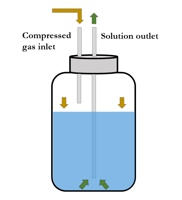
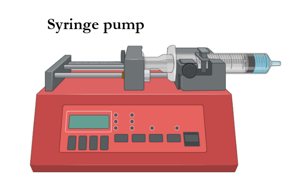
Commonly used syringe pump systems can deliver up to 140 mL of solution per batch at rates ranging from 0.1 µL/h to 6,000 mL/h. Meanwhile, pressurized liquid feeding systems contain multiple volumes of solution that range from only a few milliliters to thousands of milliliters and can furthermore be rendered in a semi-continuous mode.
Polymer melts or solutions implemented in spinning processes are delivered at constant flow rates by means of syringe pumps or pressurized liquid feeding systems. In cases involving syringe pumps, solutions are normally contained in glass or plastic syringes; whereas cases with pressurized liquid feeding systems contain the solution within a reservoir and can consequently be delivered in a semi-continuous manner.
Power Sources
A high voltage power supply with adjustable voltage is used to start the spinning process by polarizing the emitter. Researchers have used voltages up to +50 kV when creating electrospun fibers in the nano- and microscale.
To collect the electrospun fibers, a collector is typically grounded to attract them into a specific area. While it’s true that grounding a collector works well for small thicknesses, fibers are sometimes collected into unfavorable locations. To improve fiber collection, it is advantageous to apply a negative voltage into the collector. This action maximizes the emitter-collector voltage drop, thus improving fiber yield during the electrospinning process.
Emitters
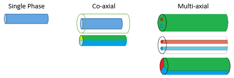
Spinning head emitters are employed in needle-based electrospinning in which multiple configurations can be implemented. These capillary needles can be configured as single, co-axial, and multi-axial phase emitters.
In single phase, only one liquid is flowing through the nozzle to form fibers with a single structure. In co-axial mode, fibers can be developed as core-shell structures — especially when encapsulation is desired — or in split structures known as Janus fibers. Multi-axial phase is the third way to create fibers where more than two solutions can be spun at a time.
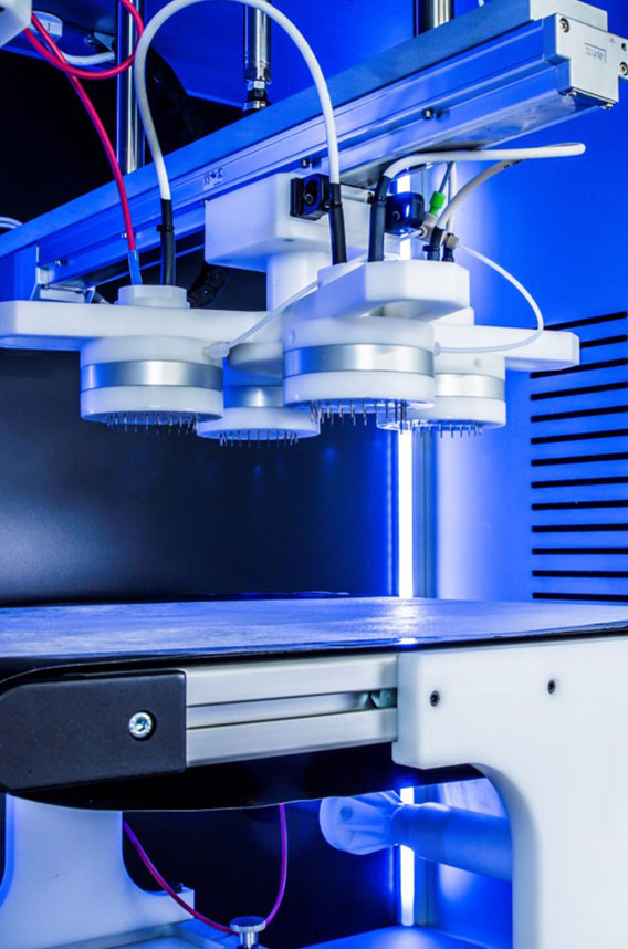
Typical electrospinning heads consist of a single capillary needle. However, to increase electrospun fiber throughput, multiple parallel emitters have been implemented in the spinning head. Since all emitters are fed from the same solution feed, production rates and fiber yield are consequently increased.
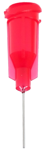
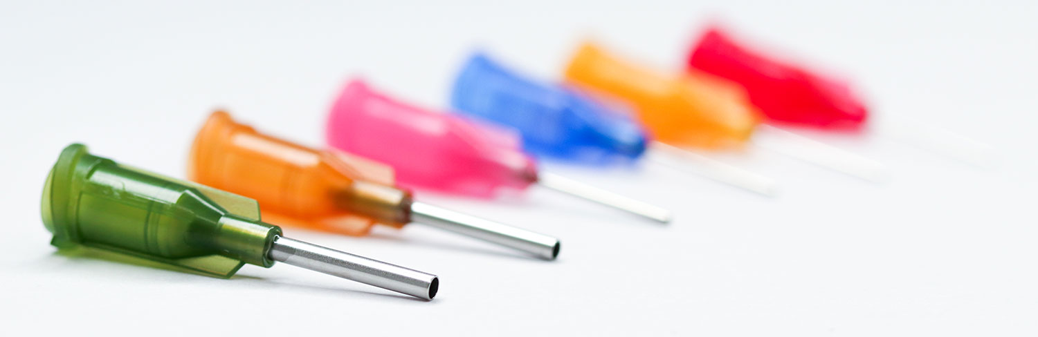
25 Gauge
Color: Red
OD: 0.52 mm
ID: 0.25 mm
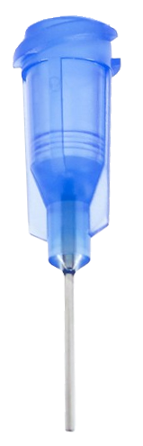
22 Gauge
Color: Blue
OD: 0.72 mm
ID: 0.41 mm
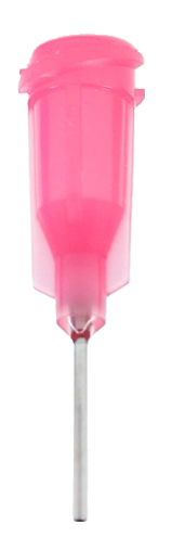
20 Gauge
Color: Pink
OD: 0.91 mm
ID: 0.61 mm
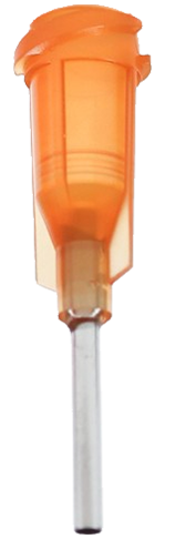
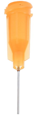
15 Gauge
Color: Amber
OD: 1.65 mm
ID: 1.36 mm
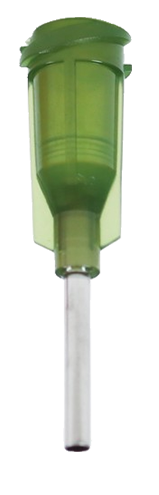
14 Gauge
Color: Olive
OD: 1.83 mm
ID: 1.54 mm
OD = Outer Diameter | ID = Inner Diameter
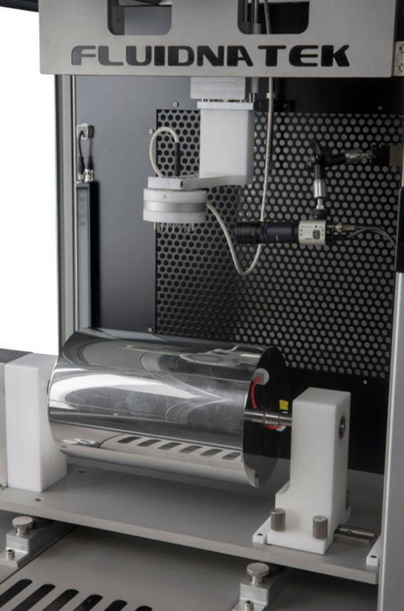
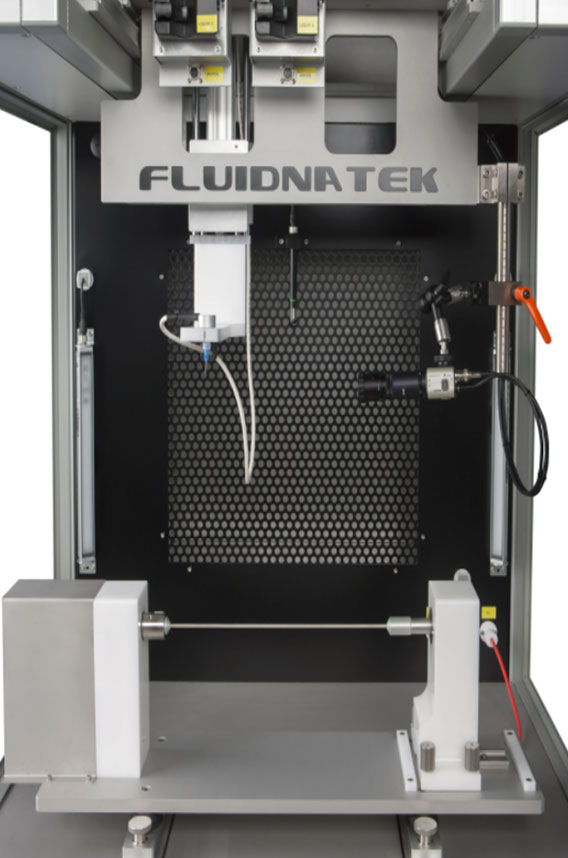
Collectors
Once solidified during the spinning process, electrospun fibers can be collected into a wide variety of collectors that mostly consist of stationary and rotating platforms. These collectors will have a significant impact in the final design of the electrospun sample. Stationary collectors are commonly flat plates to collect random fibers where the extent of the area can be tailored to a desired limit. Rotating collectors include disks, mandrels, and drums, all of which have a wide variety of dimensions. Mandrels collect fibers in random orientation due to the short diameter. Conversely, disks and drums are able to collect highly aligned structures if the diameter/length ratio and rotating speed are high enough. Larger linear speeds allow stretching of the fibers during collection and tend to encourage high degrees of alignment.
Collector Types
Flat Plate
Dimensions:
40 cm x 40 cm
(L x W)
Functions:
Random fibers, particles, and 3D structures
Drum
Dimensions:
20 cm x 30 cm
(D x L)
Functions:
Random and aligned fibers; collection of particles
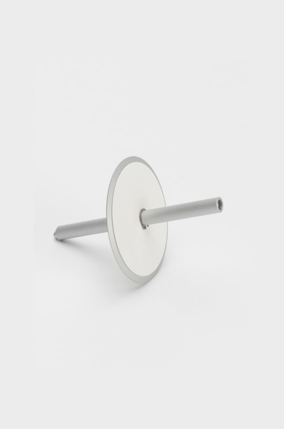
Mandrel
Dimensions:
5 mm x 30 cm
(D x L)
Functions:
Blood vessels and hollow cylindrical samples
Disk
Dimensions:
20 cm x 1 mm
(D x L)
Functions:
Aligned fibers and yarns
Roll-to-roll
Dimensions:
50 cm x roll capacity
(W x L)
Functions:
Random fibers and particles
Typical Polymers Used in Electrospinning
The electrospinning technique offers the advantage of processing a wide variety of materials including polymers and additives that are well mixed and/or suspended in solution. There are mainly three types of polymers used in electrospinning classified depending on the source: natural, synthetic and semi-synthetic polymers.
Natural polymers like gelatin and collagen are isolated from natural sources and commonly used for applications like tissue engineering as they offer biocompatibility and biodegradability properties.
Synthetic polymers, as the name suggest, are man-made polymers that are engineered to fulfill application needs. Some advantages of synthetic polymers like polycaprolactone and nylon 6,6 are their low cost and ease to tailor polymer properties like mechanical properties, degradation rates and melting point.
Semi-synthetic polymers are derived from natural polymers but chemically treated to modify its chemical structure. For example, cellulose acetate is a chemically modified polymer derived from cellulose when reacted with acetic acid.
Table of Polymers
| Type | Name | Abbreviation | Common sources | Applications•• | Solvents used* |
| Natural | Alginate | Al | Algae | TE, DD | W** |
| Chitin | CHI | Crustaceans, fungi | DD, MD, TE | HFP | |
| Chitosan | CS• | Crustaceans, fungi | DD | HFP, W | |
| Collagen | CLG | Bovine | TE | HFP, W | |
| Fibrinogen | FGN | Bovine | TE | W | |
| Soy Protein Isolate | SPI | Soybeans | TE | W** | |
| Gelatin | GEL | Bovine, Porcine | TE, MD, DD | AA, HFP, W | |
| Hyaluronic acid | HA• | Bovine | TE | W | |
| Silk Fibroin | SF• | Silkworm Bombyx mori | TE, DD | HFP | |
| Type | Name | Abbreviation | Melting Point (°C) | Applications•• | Solvents used* |
| Semi-synthetic | Cellulose acetate | CA• | 230-300 | MD, F | A, AA, HFP |
| Cellulose triacetate | CTA | 120-300 | MD, F | A, AA, HFP | |
| Ethyl Cellulose | EC | 240-255 | DD, F, MD | Ace, DMF | |
| Hydroxethl Cellulose | HEC | 140 | FP, F, MD | W | |
| Polybutylenesuccinate | PBS | 112-115 | FP | HFP | |
| Synthetic | Nylon 6,6 | PA66 | 262 | F | AA, HFP |
| Poly (2-Hydroxyethyl Methacrylate) | pHEMA• | - | MD, TE | W, EtOH | |
| Poly(butyl methacrylate) | PBMA | - | MD, TE | A, DMF, HFP | |
| Poly(methyl methacrylate) | PMMA• | 160 | MD, TE | FA | |
| Poly(vinyl chloride) | PVC | 100-260 | F | THF, DMF | |
| Polyacrylonitrile | PAN | 317 | E | DMAc | |
| Polyanyline | PANi | >330 | E | CHF, DMF | |
| Polycaprolactone | PCL• | 59-64 | TE, MD, DD | A, AA, CHF, DCM, MA, HFP | |
| Polydioxanone | PDO | 110 | TE, MD, DD | HFP | |
| Polyether ether ketone | PEEK• | 343 | MD, TE | HFIP | |
| Polyethersulfone | PES | 227-238 | E | DMAc:nMP (90:10) | |
| Polyethylene Glycol | PEG• | 65 | MD, TE | W | |
| Polyethylene oxide | PEO | 65 | MD | W | |
| Polyethylene terephthalate | PET• | 260 | TE, MD, DD | HFP | |
| Polyethyleneimine | PEI | 60 | DD, MD, TE | W | |
| Polyglycolic acid | PGA• | 224-230 | TE, MD, DD | HFP | |
| Polyhydroxybutyrate | PHB | 170-180 | TE, MD, DD, FP | HFP | |
| Polylactic acid | PLA• | 160-180 | TE, MD, DD | HFP | |
| Polylactic-co-glycolic acid | PLGA• | 225-230 | TE, MD, DD | HFP, THF | |
| Polypropylene | PP• | 160 | E, F, MD, TE | Ace, Cy, DMF | |
| Polypyrrole | PPy | >300 | E, TE | W** | |
| Polytetrafluoroethylene | PTFE• | 327 | MD | W** | |
| Polyvinyl alcohol | PVA• | 200 | MD, DD | W | |
| Polyvinylacetate | PVAc | 60 | E, F | DMF | |
| Polyvinylidene fluoride | PVDF | 177 | F | DMAc | |
| Polyvinylpyrrolidone | PVP• | 150-180 | F | CHF, DMF, W | |
| Thermoplastic polyurethane | PU• | 110-280 | TE, MD, DD | DMAc |
• | Indication of FDA approved polymers.
•• | DD = drug delivery, E = energy, F = filtration, FP = food packaging, MD = medical devices, TE = tissue engineering.
* | This is not an extensive list of solvents used to generate solutions for electrospinning. See the ‘solvent selection’ for additional information on the solvents.
** | Typically requires a carrier polymer to generate fibers.
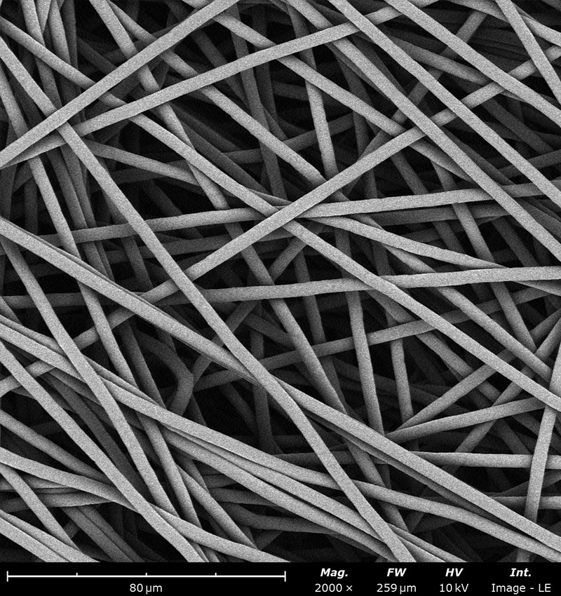
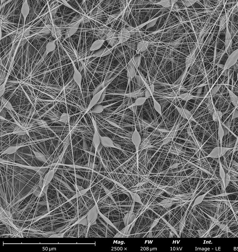
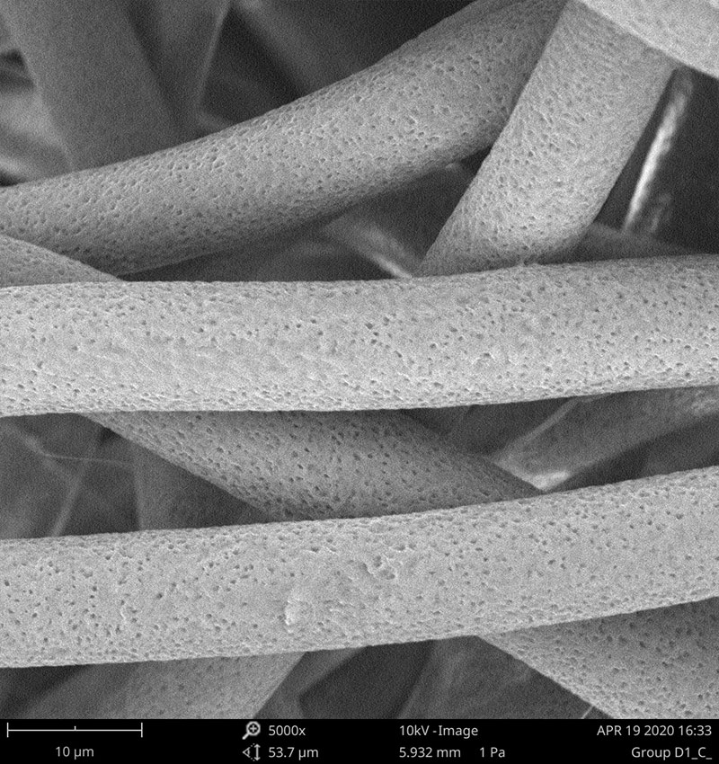
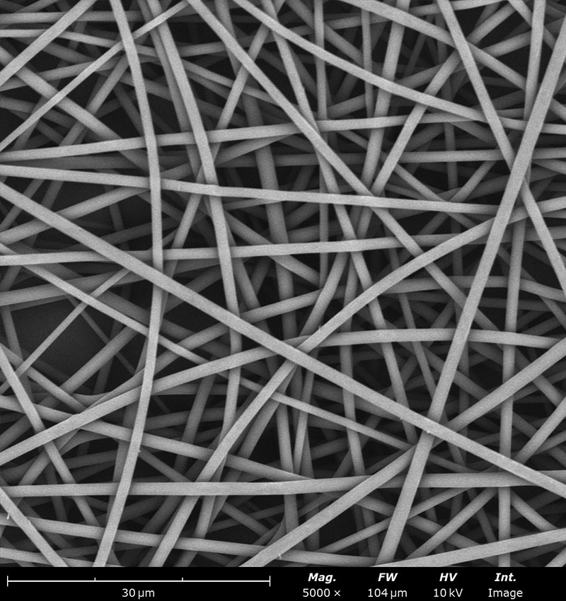
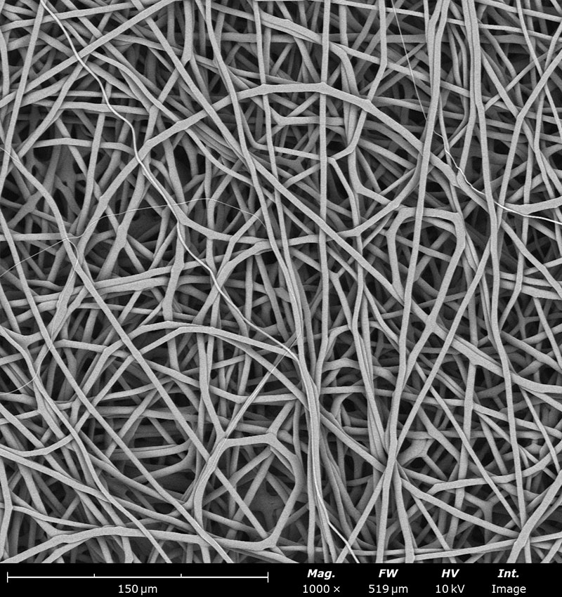
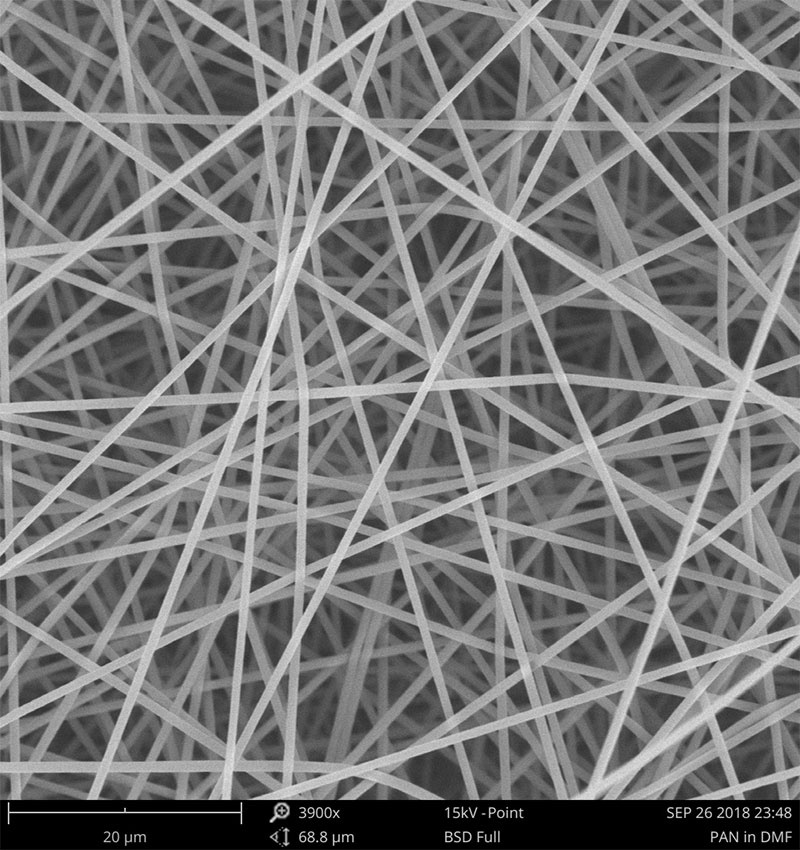
Examples on microstructural morphology of different electrospun materials
Effects of Solution Parameters
In order to obtain reproducible electrospun samples, the polymeric or non-polymeric solution to be processed needs to be reproducible by itself. Otherwise, non-consistent results are obtained, despite maintaining all electrospinning parameters the same between batches. Some of the key parameters to maintain batch-to-batch consistency for electrospun nano- and microfiber development are viscosity, conductivity, and surface tension — all of which are affected by polymer, solvent, and additive selection. Additional factors like solid content and solvent selection are measured to maintain solution reproducibility and manipulate fiber morphology, respectively. Above all else, the solution should be well mixed and homogeneous before being processed through electrospinning.
Viscosity
Viscosity is one of the key properties in electrospinning that is influenced by the molecular weight of the polymer (along with solution concentration and solvent selection of course). In theory, higher molecular weight or higher concentration translates into higher viscosity. Solvents that have more interaction with the polymer structure also tend to result in a solution with higher viscosity.
On one hand, processing with a high viscous solution encourages polymer chain entanglements to occur during the jet formation. These entanglements are the source of the fiber structures characteristic of electrospinning. On the other hand, processing a solution with a low viscosity translates to insufficient polymer entanglements during the process, resulting in the polymer jet breaking and forming particles instead of fibers. This is a different powerful process known as electrospraying.
Conductivity
Solvent and polymer content can affect the overall solution conductivity. Solutions with higher conductivity tend to generate bead-free fibers. The solvent quality and additives will also affect the conductivity of the overall solutions. This is one reason why using the same solvent grade should be maintained to allow for solution reproducibility.
For example, some solvents contain additives or stabilizers that then affect solution conductivity and its spinnability, eventually. Inorganic and organic salts, along with surfactants, can be used to selectively manipulate the solution’s conductivity. When increasing the overall charge density of the solution, jets formed during the electrospinning process can be optimized to promote bead-free fibers.
Solvent Selection
A solvent able to dissolve the polymer(s) and additive(s) while maintaining a homogeneous solution is always desired. Ideally, the solvent in the polymer solution should completely evaporate during the electrospinning process. Otherwise, generated fibers could be soaked wet and cause fused fiber-fiber bonding.
A scientist must be mindful of the solvent properties to avoid undesirable defects. Chief among important solvent properties are boiling point, conductivity, and vapor pressure. Using a solvent that has a low boiling point could result in complete evaporation. However, if it evaporates too fast, the polymer will clog the needle, thus disrupting the entire process. To remedy this issue, a solvent with a lower vapor pressure could be selected. Fiber diameter will also be affected by boiling point and conductivity. In general, lower boiling point solvents with low conductivity tend to form high fiber diameter. The opposite relation applies for vapor pressure and dielectric constant, however. As an example, polycaprolactone (PCL) fibers have been generated in the nanoscale when high boiling point solvents (like acetic acid) were used. Additionally, microscale PCL fibers formed with low boiling point solvents like dichloromethane (DCM) or 1,1,1,3,3,3-hexafluoroisopropanol (HFIP).
Table of Solvents
| Solvent name | Solvent abbreviation | Boiling point (°C) | Vapor pressure at 20°C (mmHg) | Dielectric constant | Surface tension at 20°C (mN/m) | Density at 20°C (g/mL) |
| Acetic acid | AA | 118 | 11.4 | 6.2 | 27 | 1.049 |
| Acetone | Ace | 56 | 185.5 | 21.5 | 25.2 | 0.788 |
| Chloroform | CHF | 61 | 160 | 4.8 | 27.5 | 1.489 |
| Cyclohexane | Cy | 81 | 78 | 2.02 | 24.95 | 0.7781 |
| N,N-Dimethylacetamide | DMAc | 166 | 2.25 | 37.8 | 36.6 | 0.937 |
| Dichloromethane | DCM | 40 | 353 | 8.93 | 26.5 | 1.326 |
| N,N-Dimethylacetamide | DMAc | 166 | 2.25 | 37.8 | 36.6 | 0.937 |
| N,N-Dimethylformamide | DMF | 152 | 2.3 | 36.7 | 37.1 | 0.945 |
| Dimethyl sulfoxide | DMSO | 189 | 0.42 | 46.7 | 43.54 | 1.096 |
| Ethanol | EtOH | 78 | 44.63 | 24.5 | 22.1 | 0.789 |
| Ethyl acetate | EA | 77 | 73 | 6.0 | 23.9 | 0.901 |
| Formic acid | FA | 101 | 42.97 | 57.9 | 37.67 | 1.221 |
| Glycerol | Gly | 290 | 0.0002 | 13.2 | 63.4 | 1.261 |
| Hexane | HX | 69 | 124 | 1.9 | 18.43 | 0.659 |
| 1,1,1,3,3,3-Hexafluoro-2-propanol | HFP | 58 | 120.01 | 15.7 | 14.7 | 1.596 |
| Isopropyl alcohol | IPA | 82 | 33 | 17.9 | 23 | 0.786 |
| Methanol | MeOH | 65 | 126.76 | 32.7 | 22.7 | 0.791 |
| Methyl acetate | MA | 57 | 216.02 | 8.0 | 24.8 | 0.932 |
| N-Methyl-2-pyrrolidone | nMP | 202 | 0.29 | 33.0 | 40.79 | 1.026 |
| Tetrahydrofuran | THF | 66 | 127 | 7.6 | 26.4 | 0.888 |
| Water | W | 100 | 18 | 80.3 | 72.8 | 0.998 |
References:
Dielectric constant | Vapor pressure | Surface tension I | Surface tension II
Surface Tension
As mentioned before, electrospinning is dependent upon the electrostatic force overcoming the surface tension of the solution. As a consequence, solutions with low surface tensions are usually preferred for electrospun sample development. Surface tension is affected by polymer concentration, solvent selection (single or co-solvent systems), and additives (ex. surfactants). When measuring surface tension — and depending on the solution properties — it is recommended to use the same type of needle gauge used during needle-based electrospinning process as it is known that needle gauge itself tends to affect surface tension.
Solid Content
Solid content is also measured to confirm that a solution has been prepared properly. For this, moisture analyzers are usually employed. As a rule of thumb, higher solution concentration (or solid content) translates to higher fiber diameter.
Electrospinning Processing Parameters
Once a homogeneous and well mixed solution has been obtained, the electrospinning process can be initiated. To allow for sample reproducibility, multiple electrospinning parameters must be monitored and recorded to allow for reproducible fiber morphology and batch-to-batch sample consistency. These parameters are as follows.
Voltage
Needle Voltage
In order to start the electrospinning process, a voltage needs to be applied to the needle for charges to accumulate and overcome the surface tension. A positive voltage is commonly applied; meanwhile, negative voltage could also be employed to start the process.
Higher positive voltage in the needle typically improves the stretching and the electric field, causing smaller fiber diameter to be formed. Some studies have seen the opposite, or no effect on fiber diameter, as it is dependent on the system to be processed.
Collector Voltage
Although the collector is typically grounded to collect electrospun fibers, researchers are frequently using an opposite charge to the needle in the collector (opposite charges attract each other).
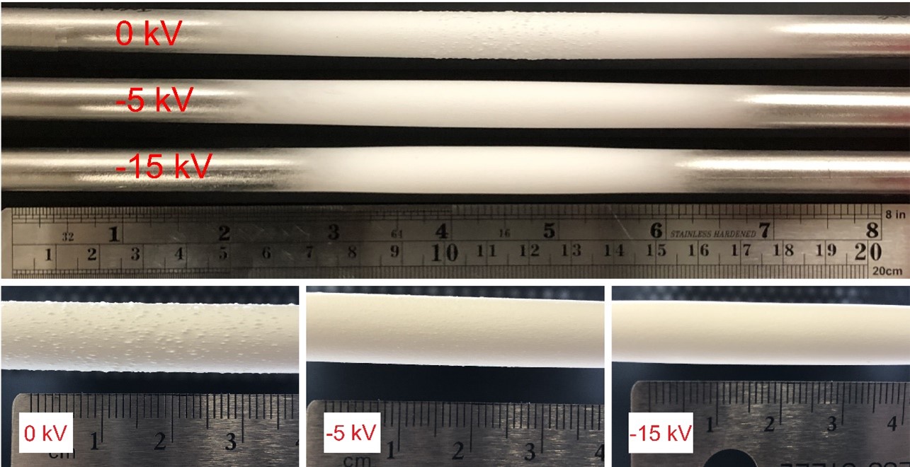
A negative voltage is key to improve sample deposition, decrease sample deposition width, properly collect all generated fibers, and prevent them from going throughout the spinning chamber due to charge repulsion, and improve final sample surface morphology as packing density can be improved (see image below).
The subsequent image conveys three cases of polycaprolactone electrospinning with variable voltages. Each session is consistent by implementations of cylindrical mandrel collectors, sessions differing only in the collector biases of 0 kV, -5 kV, and -15 kV, respectively. With increasing bias, it is evident that thinner and more focused depositions occur.
Needle-Collector Distance
Needle-to-collector distance an important key factor affecting the electric field during electrospinning processes. To obtain dry and defect-free (ex. fiber-fiber bonding) electrospun fibers, the needle-to-collector distance needs to be properly selected for the solvent to completely evaporate through the bending and whipping motion while fibers travel from the needle to the collector.
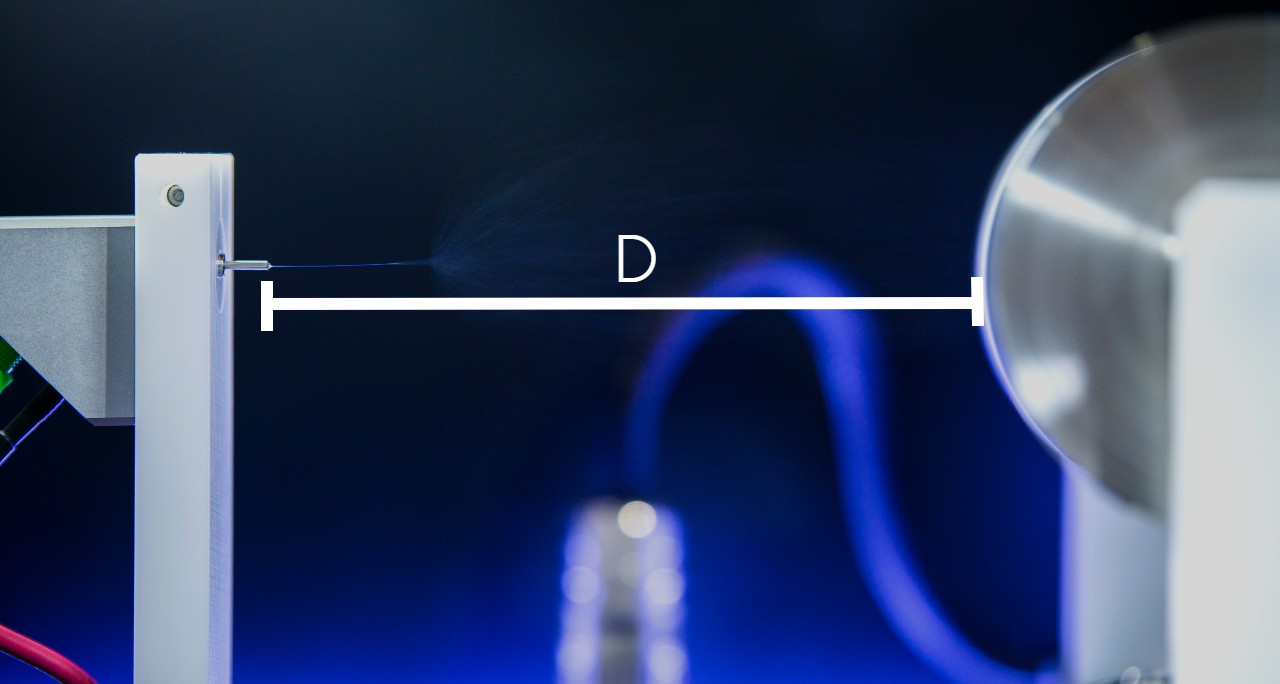
Decreasing the needle-to-collector distance results in less travel time, though also wet fibers. However, some applications benefit from lesser travel times to induce small fiber-fiber bonding. The aim of fiber-fiber bonding is to improve mechanical properties or adhere two layers between each other and avoid delamination.
Needle Translation and Speed
Most researchers perform what’s referred to as ‘static needle-based’ electrospinning. Although this is enough for sample development and optimization, the final sample will not have a homogeneous thickness because a bell-shaped thickness will be formed in its stead. If a researcher is looking into evaluating mechanical properties, drug delivery, filtration capacity of the sample, among other parameters on the final electrospun material, consistent thickness is key during sample development.
In order to improve sample thickness, needle translation allows for more homogeneous distribution (compared to static deposition). Needle displacement also aids in obtaining larger samples, and in combination with the quantity of needles used, the throughput will also be significantly increased. Typical widths of samples developed in combination with needle translation are up to 60 cm with small floor scale electrospinning equipment.
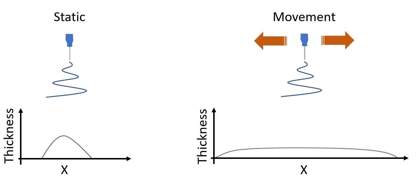
Needle displacement is combined with needle speed to obtain a well distributed thickness in the final electrospun sample. Typical translational speed are in the range of 1 to 100 mm/s. While more material will be deposited in a smaller area when the needle is translated at a slower speed, the opposite will happen at faster speeds over the same amount of time to develop a sample.
Flow Rate and Syringe Type / Size
Finding an ideal flow rate able to maintain a stable Taylor cone is ideal and is known to be solution dependent. Increasing solution flow rate during the electrospraying process commonly results in larger final particle diameter. If generating a sample with a syringe pump, it is always ideal to know your syringe material (ex. plastic, Teflon, and glass), type (BD plastic, Hamilton, among others), and its diameter (ex. syringe plunger displacement will affect the volume dispensed).
Needle Dimensions
Blunt needles are typically used for needle-based electrospinning. Needle gauges commonly used are 14 to 26 Ga (inside diameter of 1.600 to 0.260 mm; note that by going up in needle gauge, the inside diameter decreases), and with a needle length of 0.5 to 2 inches.
Selecting a proper inside needle diameter is key to prevent needle-clogging due to solvent evaporation. As a rule of thumb, low needle gauges (ex. 14 Ga) are better for solutions with high viscosity, and high needle gauge needle (ex. 26 Ga) are better for solution with low viscosity.
Collector Dimensions and Rotating Speed
Electrospun fibers can be collected in different types of collectors to fulfill application needs. Flat plate collectors are the most commonly used to obtain fibers with random orientation and with a flat surface. Typical applications where this type of collectors are used are for drug delivery, wound healing and energy storage where a large surface area is needed.
Drum collectors (outside diameter typically > 5 cm) are another example to collect fibers through the electrospinning technique. One of the advantages of using a rotating drum is that based on the drum diameter and rotating speed (ex. linear speed), random or aligned fibers can be obtained. At high linear speeds one will typically obtain aligned, or super aligned, fibers that can be used for cell proliferation or to increase sample mechanical properties like tensile strength. On the opposite side, using low linear speed will allow to obtain fibers randomly oriented. Other collectors commonly used with the electrospinning technique are small mandrels to generate artificial blood vessels or capsules for drug delivery, rotating disk to generate aligned fibers and roll-to-roll collectors to produce fibers on a semi-continuous or continuous process.
Sample Collection Substrate
Fiber packing density can be influenced by the type of substrate used in the collector. Aluminum foil is commonly used in the electrospinning field to collect fibers as it is an inexpensive conductive material. One of the main problems from using aluminum foil as the substrate is that sample removal post-processing is not easy and the material can stick to its surface, generating a deformed sample upon removal.
Non-conductive collectors can be an option to collect fibers but charges will accumulate over time making the fibers to fly away from the collector and generating lower-packing density. We have found that a combination of conductive and non-conductive material work well to improve sample collection and to allow ease of sample removal like the image shown.
Does this mean you always need to use a substrate during sample development? Not really. If your material and application needs allows, you could electrospin directly to the intended collector or onto the surface you want to coat with electrospun fibers. For example, using polymeric materials with good mechanical properties, like Polylactic acid, allow for easy sample removal from a mandrel collector like the image shown.
Another example is when coating stents with electrospun material to improve biocompatibility, in this case there’s no need to remove the fibers as they will be deposited on the intended surface.
Temperature and Relative Humidity
Monitoring processing temperature and relative humidity (RH) is key for electrospinning reproducibility. Solvent evaporation rate and solution viscosity is influenced by temperature. At high temperatures the viscosity will decrease, allowing the user to obtain smaller fibers as the stretching of the jet is increased. Relative humidity influences the solvent evaporation rate, which will have an impact on fiber microstructure and continuous spinnability.
For example, if using a low boiling point solvent in solution and electrospinning at low RH may cause needle clogging. This is not ideal as the Taylor cone will not be maintained over time, causing the process to not be continuous. Meanwhile, if a high RH is used water droplets can accumulate in the surface of the fiber which will lead to fibers with a porous microstructure. The ideal goal is to optimize the environmental conditions to allow for a stable Taylor cone where no needle-clogging occurs over time, the solvent is successfully evaporated during the process and non-desired defects (ex. fiber-fiber bonding, fiber beading, fiber bundles, particles, among others) are encountered in the sample.
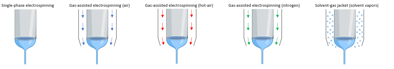
Air Flow
Air flow is also used in coaxial mode where the solution to be electrospun travels through the core needle and a gas (ex. air and nitrogen) flow through the needle. This process is known as gas assisted electrospinning where the pressurized gas aids the electrospinning process by improving solvent evaporation. Applying a hot air is also another alternative known as hot-air gas assisted electrospinning that furthers improve solvent evaporation when needed. A third option is by using solvent vapors around the needle to prevent needle clogging with solutions that easily clog the needle during electrospinning. Finally, blow spinning is an alternative method where no voltage is applied in the needle, but only pressurized air during sample development.