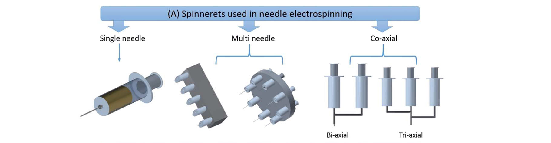
There are two distinctive ways fibers can be made using the electrospinning technique: needle-based electrospinning, or needle-less electrospinning. The ways in which the two setups differ could make one more suitable for a particular application than the other, but both are easy methods for fabricating functional nanomaterials. The diagram below highlights the flexibility of the electrospinning technique and the many different setups that are possible with both needle-based and needle-less electrospinning systems.
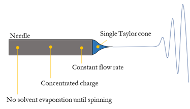
As the name suggests, needle-based electrospinning involves the use of a capillary tube (also known as a needle, nozzle, or emitter). There are many types of capillary tubes that are conducive to a good electrospinning process, including disposable polypropylene pipette tips, and reusable needles made of Teflon or stainless steel with a polypropylene hub connection. Once the needle or emitter of choice is connected to its holder, the solution flows through it at a predetermined flow rate and ideally should form a Taylor cone when the voltage has been applied.
Figure 2. Example of needle-based electrospinning with a single-needle.
The formation of a steady Taylor cone is an important indicator of a stable and continuous electrospinning process. Using this needle-based setup, it is also possible to form fibers with a core and a shell (also known as coaxial fibers), or even multi-axial fibers with multiple cavities.
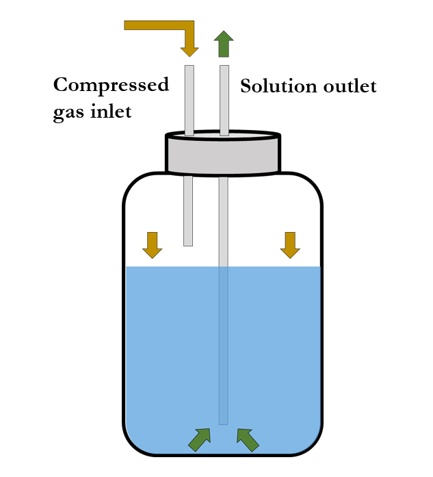
Solution is contained inside an air-tight reservoir
In needle-based electrospinning setups, the solution is contained in an air-tight and enclosed reservoir, which minimizes solvent evaporation over time. This ensures that the carefully formulated solution maintains its desired properties such as concentration, viscosity, and surface tension. The stability of the enclosed solution also supports batch-to-batch consistency once the electrospinning processing parameters have been optimized for sample development. In practice, maximizing batch-to-batch consistency and maintaining sample reproducibility is most easily achieved by using fresh and well-mixed solutions that are no more than 3 days old. Another key benefit of keeping the solution enclosed is that it provides a safe method for the use of a wide variety of highly volatile materials like chloroform, dichloromethane, and methyl acetate.
Taylor cone formation with needle-based electrospinning
In a perfect electrospinning process, the number of Taylor cones formed should directly correlate to the number of needles used in the setup. In this ideal scenario, each Taylor cone forms due to a concentrated charge (commonly DC high voltage) at the needle and the solution moves through at a constant flow rate. For industrial applications that require high-throughput fabrication of nanomaterials, many different configurations of multi-needle setups can be implemented with a few needles, dozens of needles, or even thousands of needles, as is in the case of the industrial-scale Fluidnatek High-Throughput (HT) shown below.
Tight control over flow rate during processing
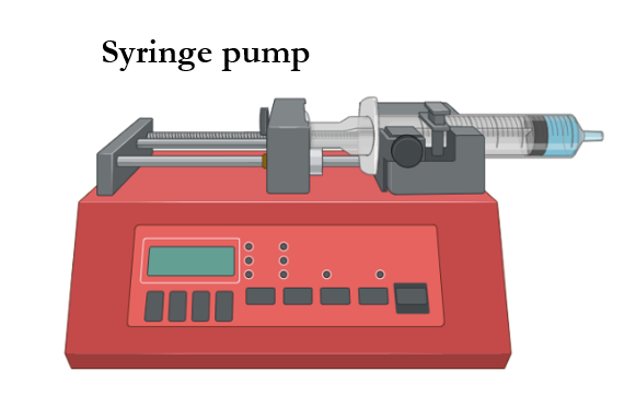
Needle-based electrospinning systems offer control over the feeding rate of the solution from which fibers are formed. In most cases, the solution is contained in a syringe which is connected to a pump that infuses a fresh amount of solution/suspension into the needle to be electrospun. This can be highly beneficial if the variation in desired fiber diameter should be very small, as the flow rate is one of the key parameters that determine the morphology of the fiber produced during a given process. Conversely, with needle-less electrospinning setups, which we will discuss in further detail later in this overview, there is typically no flow rate to control because the solution is held in an open container with its surface exposed to air. This open container configuration will promote solvent evaporation, resulting in a higher viscosity solution over time and potential fluctuation between smaller and larger fiber diameters formed across the final sample.
Multiple needle orientations can be used
There are three typical needle orientations used in needle-based electrospinning sample development: horizontal, vertical (top-down or bottom-up), and angular. Each orientation has its benefits for specific types of electrospinning processes, which we will elaborate upon below.
Horizontal electrospinning
Vertical top-down electrospinning
Needles at an angle for dual solution processing of electrospun yarns
Figure 3. Example of different needle orientations for sample processing.
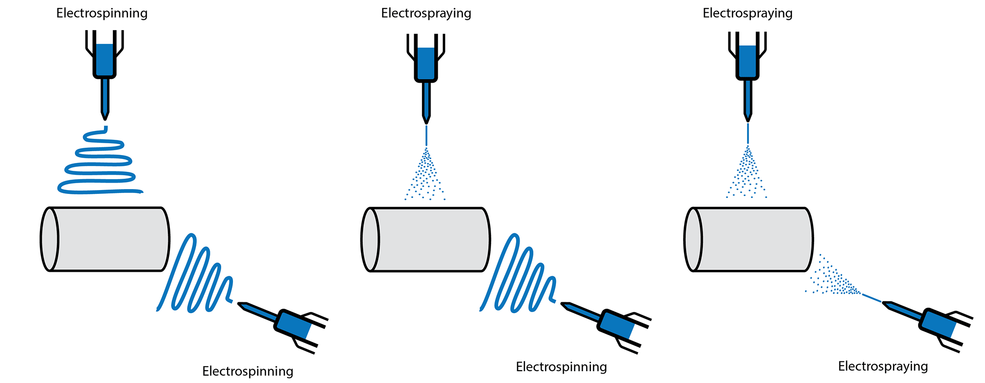
Horizontal electrospinning is the most common orientation used to process electrospun materials, especially during solution development and optimization of processing parameters. If a solution has low viscosity and begins to drip from the needle, the horizontal needle orientation prevents gravity-driven drops from falling onto the collector and potentially ruining the sample being produced.
Vertical top-down electrospinning is another option for processing electrospun fibers. One of the drawbacks of this needle orientation is the solution dripping due to gravity if the solution has not been optimized, as drips could ruin the processed sample. To prevent dripping onto a processed sample, it is recommended that needle translation be employed in a way that the initial or final drips can be collected outside the area of interest for the final sample area to remain intact. Other methods to optimize sample processing parameters and prevent dripping during top-down electrospinning include manipulating the needle-to-collector distance, flow rate, voltage, temperature and relative humidity. Solution processing parameters like viscosity, concentration, conductivity, and/or surface tension, can be optimized for the same purpose. A distinct advantage of top-down electrospinning is its utility for collecting fibers (and/or electrosprayed particles) onto a liquid container or coagulation systems.
Vertical bottom-up electrospinning is an alternative to top-down electrospinning for solution optimization as it could eliminate the risk of drops falling onto the sample due to gravity. However, it can introduce workflow challenges in certain applications. For example, an uncontrolled flow rate causing dripping down the side of the needle could promote secondary jetting during the electrospinning process, creating inconsistencies in fiber diameters throughout the final sample. The bottom-up configuration has been effective for industrial-scale production of electrospun material, especially in the filtration space (e.g. Proveil filtration material produced using the Fluidnatek HT) since it enables deposition of fibers onto large surface areas without risking drips on the final sample when tightness in fiber diameter variation is not required, and if side dripping is present.
Electrospinning at an angle is the last configuration we will discuss for collecting electrospun fibers. As shown in the video above, electrospinning at an angle allows the fabrication of electrospun yarn materials while preventing possible dripping onto the collector during solution optimization. Electrospinning setups with two needles can enable dual solution processing, where two solutions are processed with independent voltages to generate samples that maintain distinctive properties of each polymer or material processed from each solution. This approach can be applied to many other combinations of electrospun or electrosprayed final products, including: a combination of electrospun fibers and electrosprayed particles, two types of electrosprayed particles, or even a combination of electrospun fibers seeded with electrosprayed cells, among others.
Figure 4. Example of possible combinations when processing two solutions with independent voltages to improve sample properties through needle-based electrospinning.
Figure 5. Example of dual processing with needle translation to enhance deposition homogeneity.
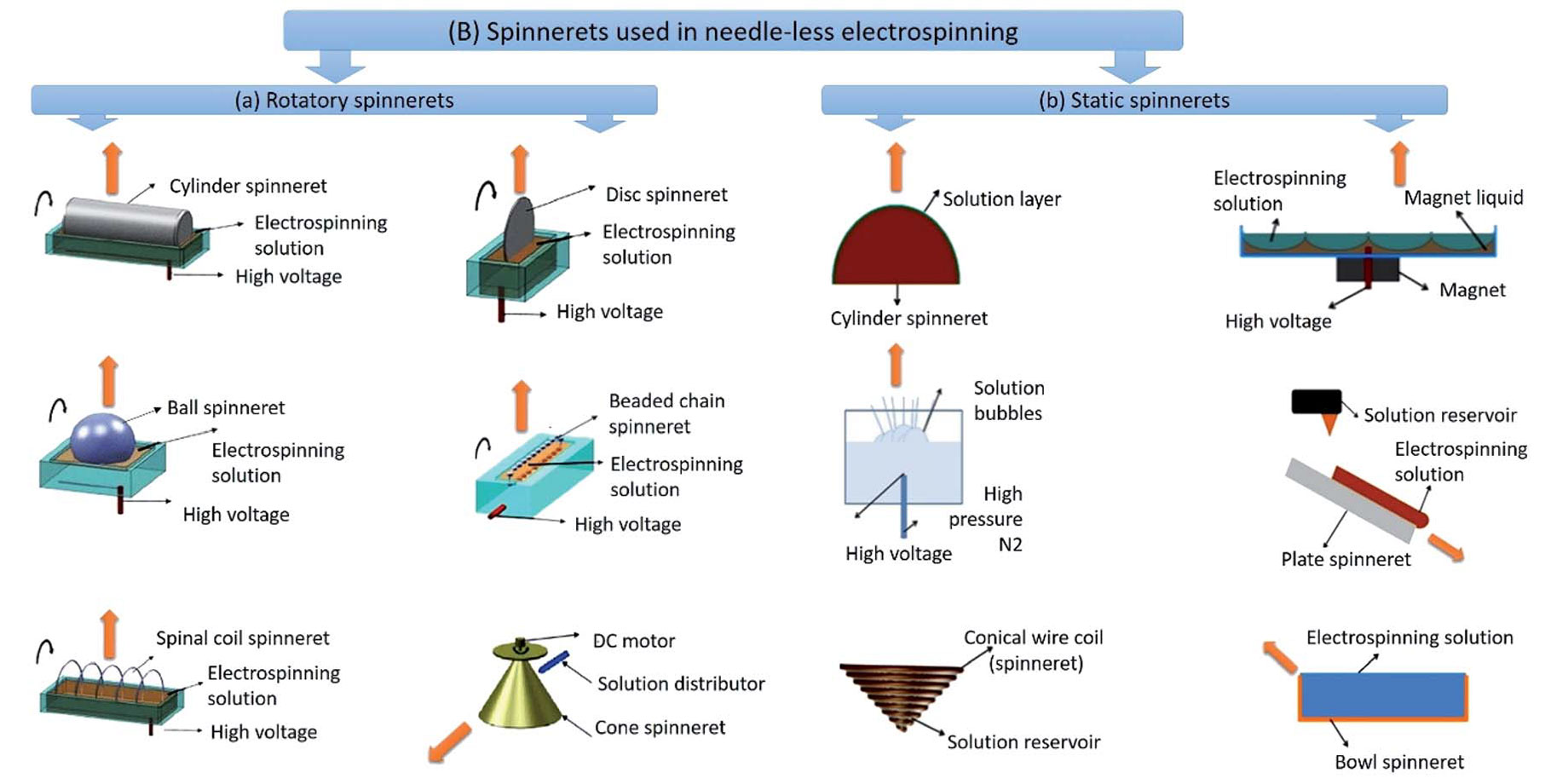
Needle-less Electrospinning
As its name suggests, there are no needles involved in needle-less electrospinning. Rather, the electrospinning process initiates at the surface of an open vessel filled with the prepared solution where fibers are fabricated by either stationary or rotating spinnerets. To ensure stable Taylor cone formation and subsequent fiber generation in this type of electrospinning setup, it is key to properly concentrate the electric charges on the liquid surface.
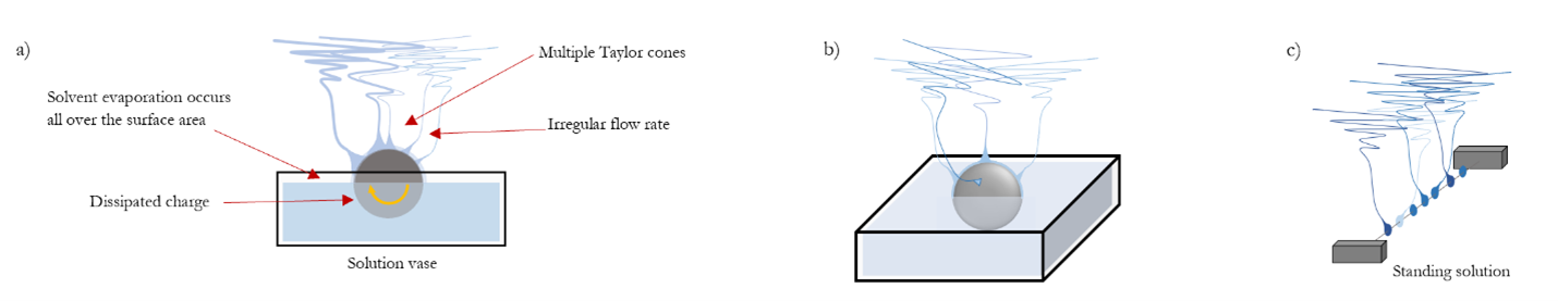
Figure 6. Three examples of needle-less electrospinning. a) a rotating spinneret via cylinder electrospinning, and two stationary methods, b) ball electrospinning, and c) solution-over-wire electrospinning.
Solution is commonly contained in an open reservoir
Needle-less electrospinning typically involves the use of an open reservoir instead of syringes of solution. This is particularly standard in setups where a rotating spinneret is used. Once the open container is filled with solution, it is expected that the solvent will begin to evaporate off the surface of the liquid, especially if the solvent has a lower boiling point and/or high vapor pressure. This constant evaporation reduces batch-to-batch consistency, impacts the reproducibility of fiber morphology throughout a sample, and has implications for specifications required by certain applications such as thickness homogeneity or grams per square meter (gsm) in the case of filtration applications.
Taylor cone formation with needle-less electrospinning
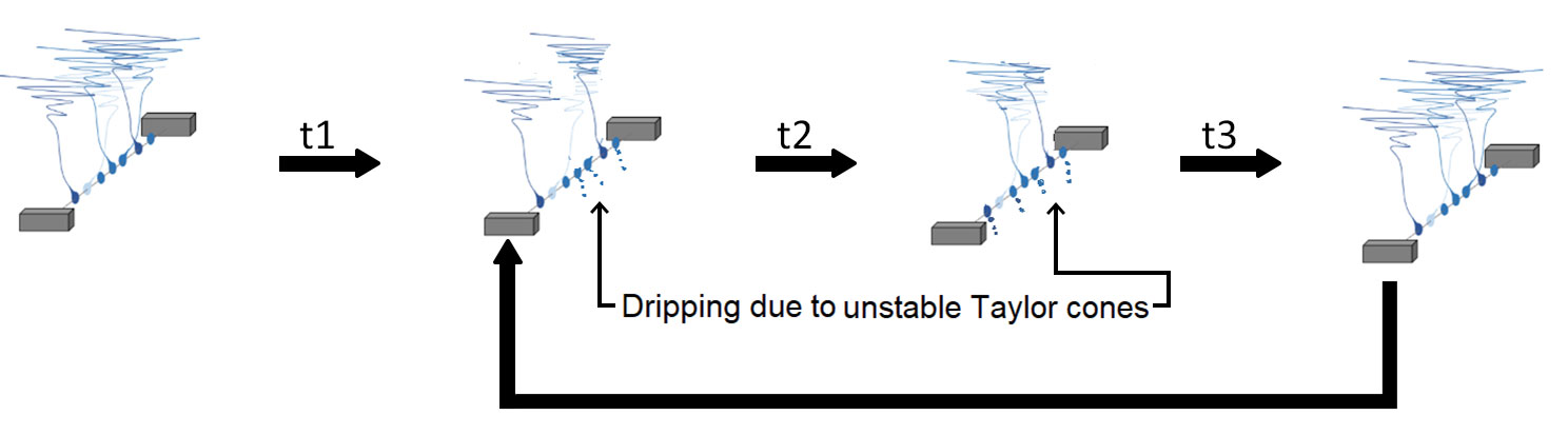
In needle-less electrospinning, Taylor cone formation is a spontaneous process that requires charges to be properly concentrated on the surface of the liquid to initiate the electrospinning process. If the Taylor cone is not stable over time, fiber formation will be inconsistent, resulting in defects such as fiber-fiber bonding and fiber beading. The consequences of this can manifest in many ways, including affecting the mechanical strength of the final sample, or changing how encapsulated drugs diffuse when employed in drug delivery applications, to name a few.
Figure 7. Diagram showing typical unstable Taylor cone formation with needle-less electrospinning processes
Flow rate control and processing throughput
Commonly the most desirable attribute of needle-less electrospinning systems is the lack of clogging, which enables continuous high-throughput of electrospun fibers with little to no user intervention. However, it does not offer the control and fine-tuning of the process that needle-based electrospinning does. For example, without a needle, there is no precise control over Taylor cone formation, nor constant charge accumulation at the spinneret. With a needle-less setup, fiber production also depends heavily on the electric field pulling force over the solution, which often translates to requiring the application of higher voltages compared to the minimum necessary voltage for needle-based electrospinning.
Complex fiber structure formation is typically not seen
While needle-less electrospinning setups are well-suited for certain applications, they may not be the most effective for generating complex fiber structures like Janus fibers, coaxial, or multi-axial fibers. They are also not ideal for electrospun encapsulation of expensive materials like active pharmaceutical ingredients for drug delivery, or growth factors for medical treatments. The lack of control over the formation of Taylor cones in needle-less electrospinning and the inability to fine-tune flow rate make needle-based electrospinning the better setup for these types of applications.
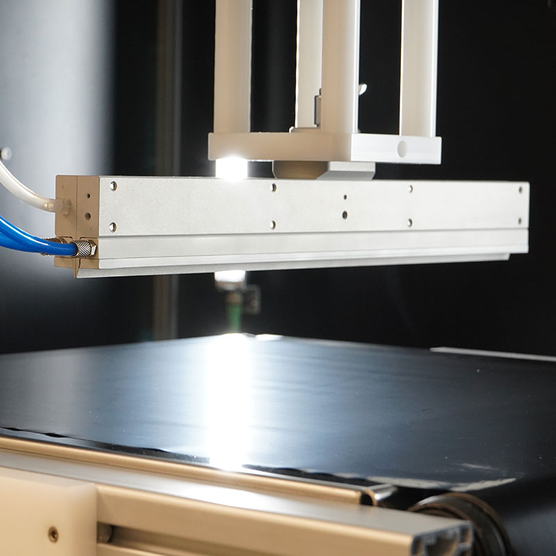
Slit Injector from Fluidnatek
Figure 8.The slit injector design.
In an effort to capitalize on the benefits of both needle-based and needle-less electrospinning, the slit injector was developed, which ushers in a new generation of needle-less electrospinning processes. The slit injector overcomes some of the hurdles of needle-less electrospinning by flowing the solution through a small slit of fixed length, which accumulates all electric charges in a much smaller area than the surface area of the open solution vessel that is traditionally used. With this narrow slit emitter, charges accumulate and easily concentrate, resulting in the formation of a Taylor cone that remains stable over time. The stable Taylor cone allows increased sample throughput and proper control over flow rate.
In addition to maintaining control over the flow rate of the solution moving through the slit injector, users are also able to prevent solvent evaporation over time since the solution can be fed from a closed reservoir, which is similar to the solution-feeding system in needle-based electrospinning. However, the slit injector does not require the use of needles to achieve stable Taylor cones, so labs can eliminate the setup time that is usually associated with multi-needle assemblies, and conserve resources such as consumable needles, minimizing the cost per process. Crown, or drying defects, will also be significantly reduced with solutions that tend to evaporate quickly, or when control over environmental conditions is not possible.
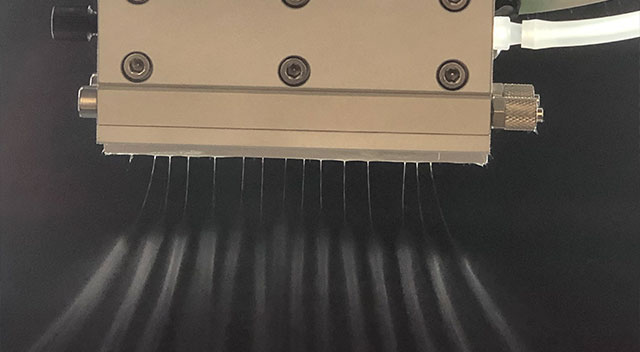
The slit injector designed by the Fluidnatek team also supports processing of solutions by electro-blow spinning via gas-assisted processing to further improve sample throughput over conventional needle-less electrospinning setups.
Figure 9b. Video of the process of an electrospun sample with two simultaneous slit injectors while collecting the fiber material on a roll-to-roll system.
Figure 9. a) Processing PAN fibers with the slit injector of 10 cm in length and b) Video of the process of an electrospun sample with two simultaneous slit injectors while collecting the fiber material on a roll-to-roll system.