Introduction
Polymer fibers are produced from synthetic or natural polymers and engineered to deliver a wide range of mechanical, chemical, and functional properties. Polymer chemistry, molecular weight, and additives can be modulated to achieve specific strength, elasticity, thermal stability, biocompatibility, or chemical resistance. This versatility enables polymer fibers to be lightweight yet strong, cost-effective, and scalable; making them suitable for applications ranging from high-performance textiles and composite reinforcement to medical devices, filtration media, and energy storage systems.
A variety of fabrication techniques are used to produce polymer fibers, each offering distinct advantages. Melt spinning is widely used for thermoplastics and supports high-throughput, industrial-scale production with precise control over fiber diameter and mechanical properties. Solution spinning methods, such as wet and dry spinning, enable processing of a wider range polymers and allow incorporation of functional additives. Electrospinning produces micro- to nanoscale fibers with high surface area and controlled porosity, making it particularly valuable for biomedical applications, medical devices, tissue engineering, drug delivery, and filtration. As a result of its material versatility, tunability, and precision, electrospinning has become a top choice for nanofiber production applications.
What is Electrospinning?
Fiber Structure and Morphology
The electrospinning technique allows the production of fibers of different structural morphologies to meet different application needs. Single-phase and coaxial electrospinning are two widely used approaches for fabricating polymer fibers, each offering distinct structural capabilities and application benefits.
In single-phase electrospinning, one polymer solution is used to produce uniform fibers. The polymer solution could be composed of either a single polymer, a blend of polymers, or polymer-additive blends. This is a straightforward and scalable method for applications such as filtration membranes, nonwoven textiles, and surface coatings. For additional versatility, multiple solutions can be spun simultaneously through independent emitters, a process also known as co-spinning. Coaxial electrospinning, by contrast, employs a concentric nozzle to simultaneously spin two different materials, enabling the formation of core-shell fibers.
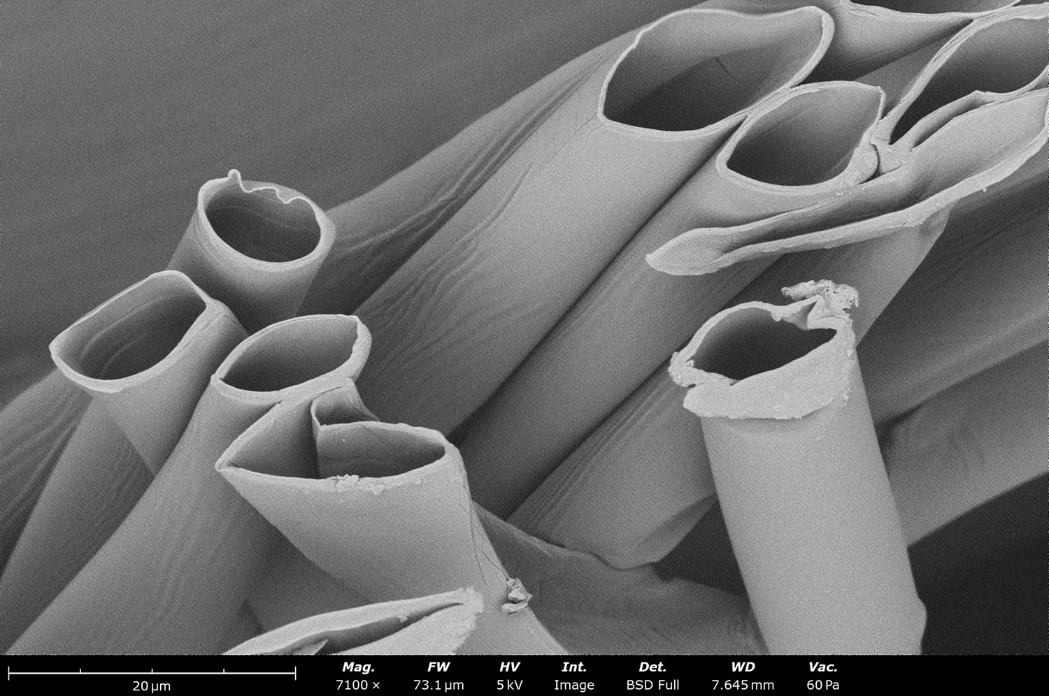
Figure 1 shows an example of hollow polylactic acid (PLA) fibers. This architecture allows functional components such as drugs, catalysts, or conductive materials to be encapsulated within a protective shell, improving stability and controlled release. As a result, coaxial electrospinning is particularly advantageous for applications in drug delivery, tissue engineering, energy storage, and smart materials, where multifunctionality and precise spatial control of materials are required. Multi-axial fibers composed of three or more phases are also a possibility with the electrospinning technique.
Fiber Structure and Morphology
Environmental Factors
Controlling relative humidity and temperature is critical for consistent and reproducible fabrication of fibers by electrospinning. The most important reason for controlling these parameters is the significant impact they have on the solvent evaporation rate of the polymer solution during electrospinning. Controlling this evaporation rate will lead to a more stable Taylor cone during deposition, which results in more consistent and defect-free fiber/particle deposition.
Figure 2 shows the effect of environmental conditions on electrospinning polycaprolactone (PCL) solution. In dry conditions when temperature and relative humidity (RH) are not well controlled, the polymer solution dries quickly, preventing the formation of a stable Taylor cone. The fibers fabricated under these conditions show significant defects (Figure 2A). When temperature and relative humidity are well controlled, a stable Taylor cone is formed and fabricated fibers are uniform and defect-free (Figure 2B).
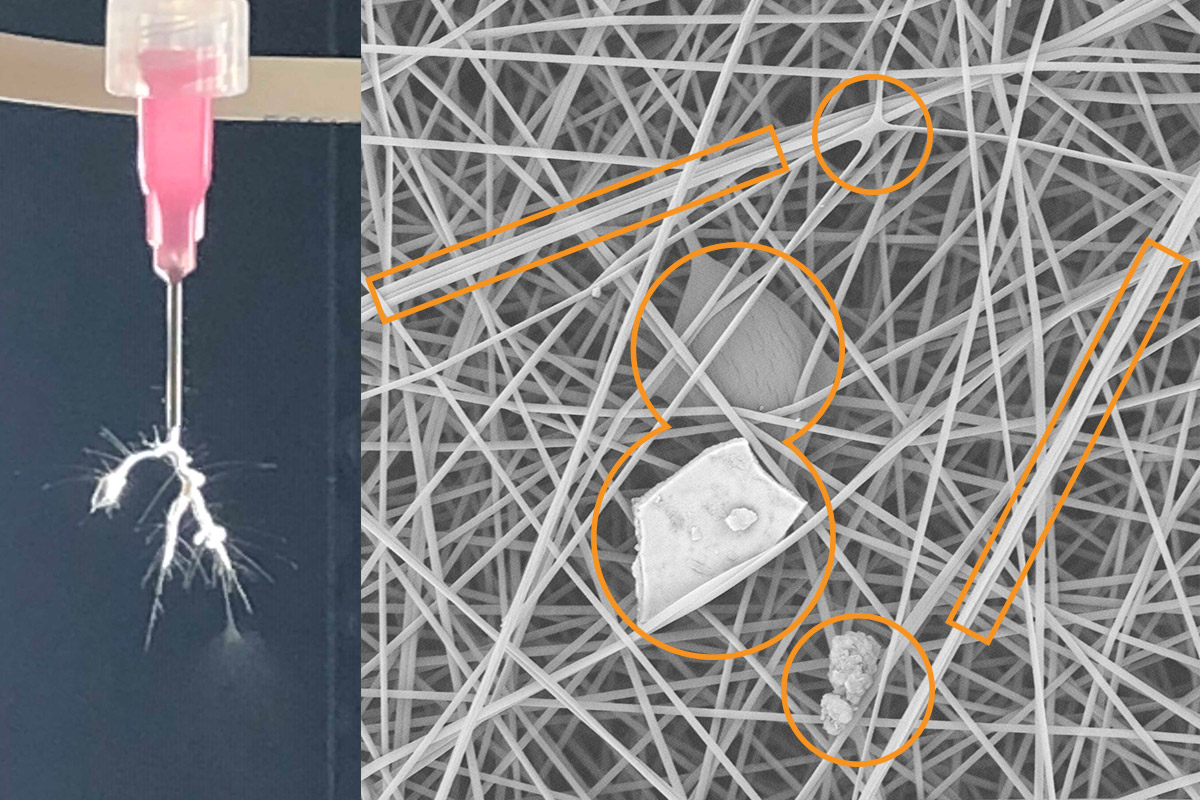
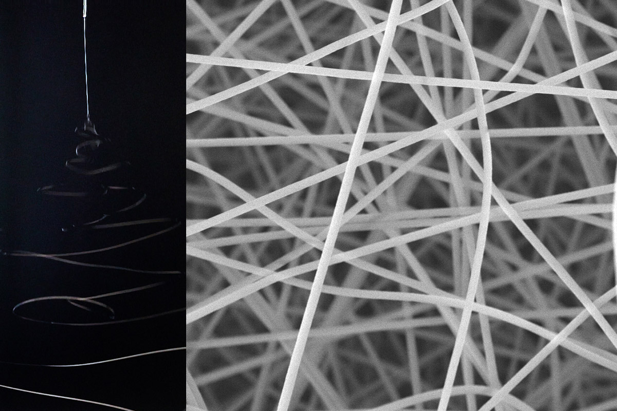
Figure 2. Electrospun polymer fibers produced without temperature and RH control causing instability and non-reproducible results (A).
Electrospun polymer fibers produced with temperature and RH control resulting in a stable Taylor Cone and reproducible results (B).
Control over relative humidity is also important as it influences charge dissipation during processing, which helps prevent microstructure imperfections. Control over relative humidity and temperature can help prevent the formation of specific defect types such as beading, fiber bundles, or fiber-fiber bonding, as seen in Figure 3.
Figure 4 shows the electrospinning results for PCL under varying environmental conditions. At 25 °C and 30% RH, the fibers exhibit a broad diameter distribution. Increasing the RH to 70% or raising the temperature to 35 °C leads to the formation of more uniform fibers. In contrast, electrospinning at 45 °C combined with a reduced RH of 10% results in pronounced fiber–fiber bonding.
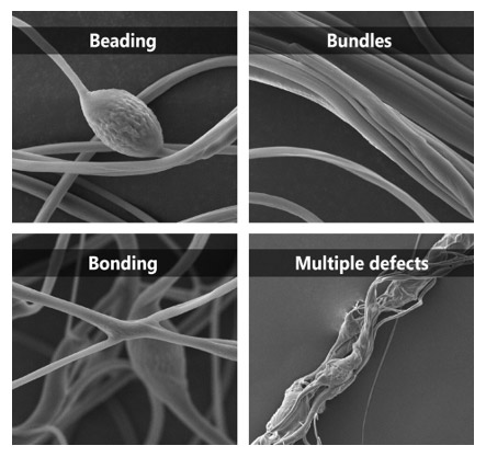
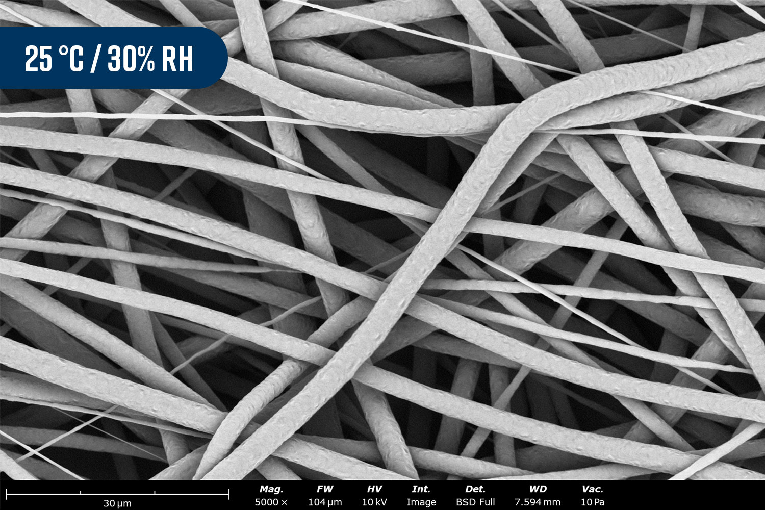
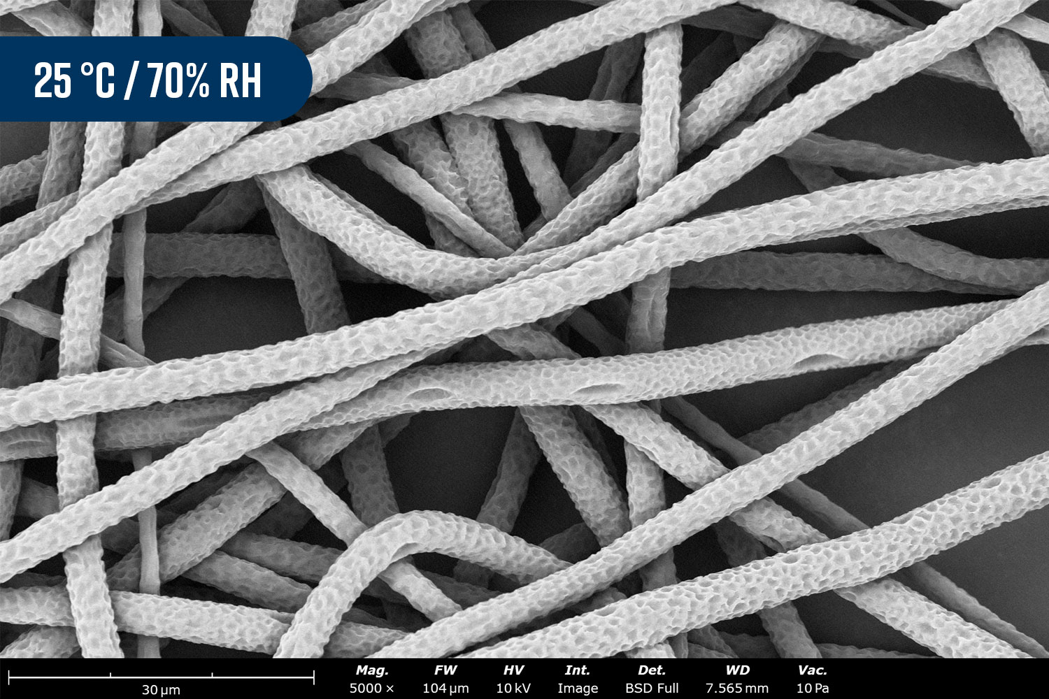
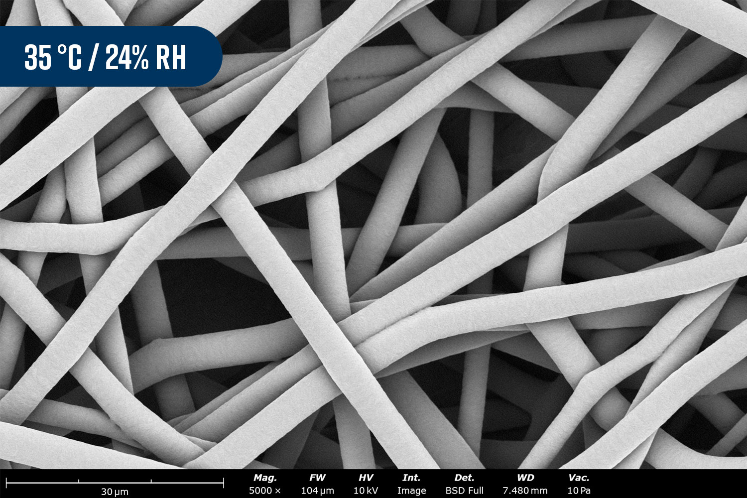

Figure 4. Electrospun PCL fibers fabricated under various temperatures and relative humidities.
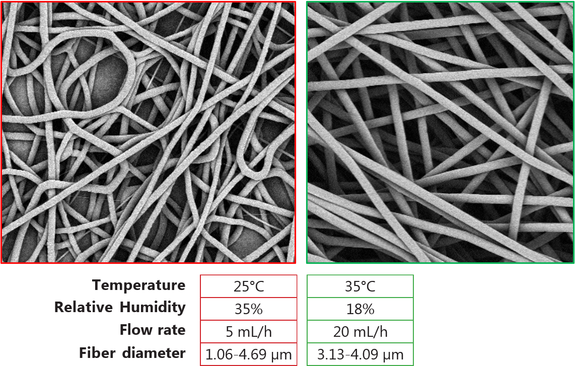
Solution spinnability and production can also be improved by increasing the temperature. For example, Figure 5 shows that by optimizing electrospinning parameters via control over temperature and RH, production throughput can be increased four times while providing uniform fiber diameters throughout the sample. This is important for various applications, especially for filtration purposes.
Multi-needle electrospinning/electrospraying systems (5 to 5,000+ needles) increase production throughput by covering a larger area in the same amount of time. Controlling temperature and humidity is critical in multi-needle electrospinning because environmental conditions directly influence jet stability, solvent evaporation, and fiber–fiber interactions, all of which are amplified when multiple jets operate simultaneously. Multi-needle systems need greater volumes of air need to be environmentally conditioned and increase the need for solvent vapor removal in the fabrication chamber.
Solvent Properties
Solvent selection plays a critical role in electrospinning, as it directly influences solution properties and fiber formation dynamics. Key solvent parameters, including volatility, dielectric constant, surface tension, viscosity, and polymer–solvent compatibility, are influential to electrospinning parameters such as Taylor cone and jet stability, stretching, and solvent evaporation. Highly volatile solvents can promote rapid solidification but may also lead to jet instabilities or porous fiber morphologies, while low-volatility solvents can result in incomplete solvent removal and fiber-fiber bonding on the collector. In addition, solvent conductivity and surface tension influence the extent of jet elongation and final fiber diameter. Solutions with high surface tension are typically not spinnable, but chemical additives such as salts can be added to decrease surface tension.
The choice of solvent determines the fiber dimensions since the solvent’s boiling point and vapor pressure have direct effects on sample morphology (fiber diameter and pore size), which determines surface porosity and mechanical properties. For example, Figure 6 shows images of PCL spun with acetone (Figure 6A) and dichloromethane (Figure 6B) while keeping all other parameters constant. The use of a lower boiling point solvent causes faster evaporation during the spinning process, which results in increased fiber diameter and rougher surfaces. Careful optimization of the solvent or solvent mixture is therefore essential to achieving uniform fibers with controlled morphology and reproducible electrospinning performance.
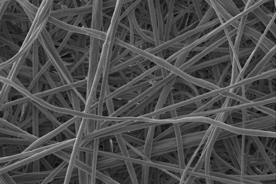
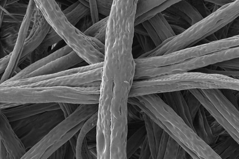
Figure 6. Effect of solvent (A) Acetone (B) dichloromethane on electrospinning Polycaprolactone. The use of dichloromethane which has lower boiling point results in larger fiber diameter and rougher surface morphology.
Electrospinning Systems
Fluidnatek offers versatile line of instuments consisting of standard, biomedical, entry-level, and high throughput electrospinning systems engineered with reproducibility, flexibility, versatility, and traceability in mind. Users have control over the entire electrospinning process, enabling reproducible and precisely tunable fabrication of polymer fibers and particles. The standard line is designed for seamless transition from research-scale to pilot and industrial production of nanofibers and nanoparticles. The LE-50 is a compact benchtop system designed for advanced R&D projects, ideal for proof-of-concept and feasibility studies. The LE-100 is designed for lab-scale and small-batch production and is the ideal choice for advanced R&D projects and product development. For larger scale needs, the Fluidnatek LE‑500 expands capacity with up to 370 nozzles, high-volume solution handling, supporting pilot-scale manufacturing or pre-series production under controlled, clean conditions. The environmental control unit (ECU) available for the Fluidnatek electrospinning systems, offers precise and consistent control over environmental conditions. Air from the room is conditioned inside the ECU to humidify, dry, heat or cool depending on application needs. Conditioned air is constantly monitored by measuring present value (PV), providing constant control over temperature, relative humidity, and air flow conditions. The operational ranges of the ECU are 18 – 45 °C (±1 °C), 10 – 80% (±3%) relative humidity, and air flow 80 – 200 m3/h. The integrated HEPA filter maintains processing conditions under ISO-7 cleanliness standards.
Characterization of Electrospun Fibers
Fiber Morphology
Scanning electron microscopy (SEM) is widely used to characterize electrospun fibers because it provides the high spatial resolution and depth of field required to accurately assess fiber morphology at the micro and nanoscale. Electrospun materials often consist of non-woven networks with fiber diameters ranging from tens of nanometers to several micrometers, a range where optical microscopy lacks sufficient resolution and contrast. Figure 7 shows the difference between optical and SEM imaging of the same fiber sample.
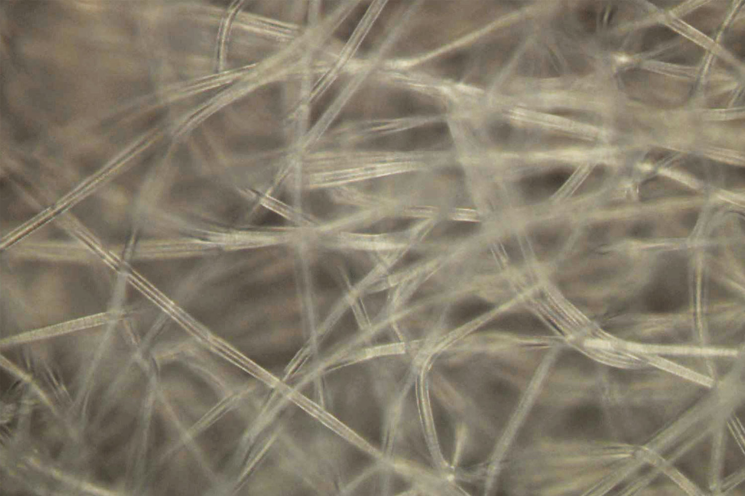
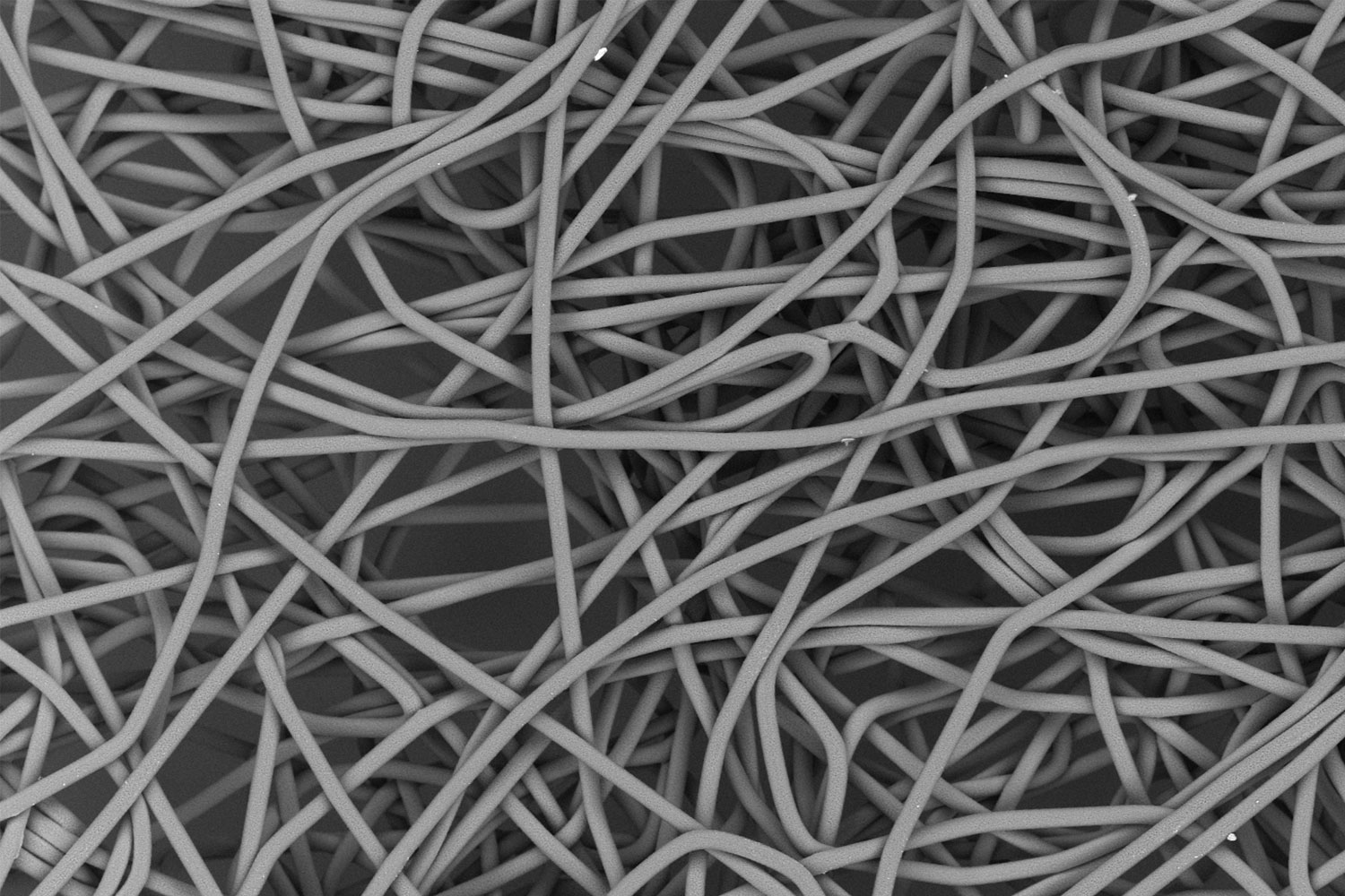
Figure 7. Comparison of images of electrospun fibers obtained by optical microscopy (A) and SEM (B).
Mechanical Properties of Fibers
Tensile testing is a widely used technique for assessing material properties and predicting how products will behave under stress. Typically, materials are pulled until failure by one instrument, then analyzed under SEM to determine the microstructural points of failure. However, with the tensile testing stage for the Phenom XL desktop SEM, both steps can be performed by the same instrument. This is particularly valuable for analyzing the deformation of single fibers or filament strands. Figure 8 shows the tensile testing of polycaprolactone-polyethelyne terephthalate electrospun fibers using a Phenom SEM. Figure 8A is the optical image of the PCL-PET mat loaded on the tensile stage and Figure 8B is an SEM image of the individual fibers under stress, where deformation is clearly visible.
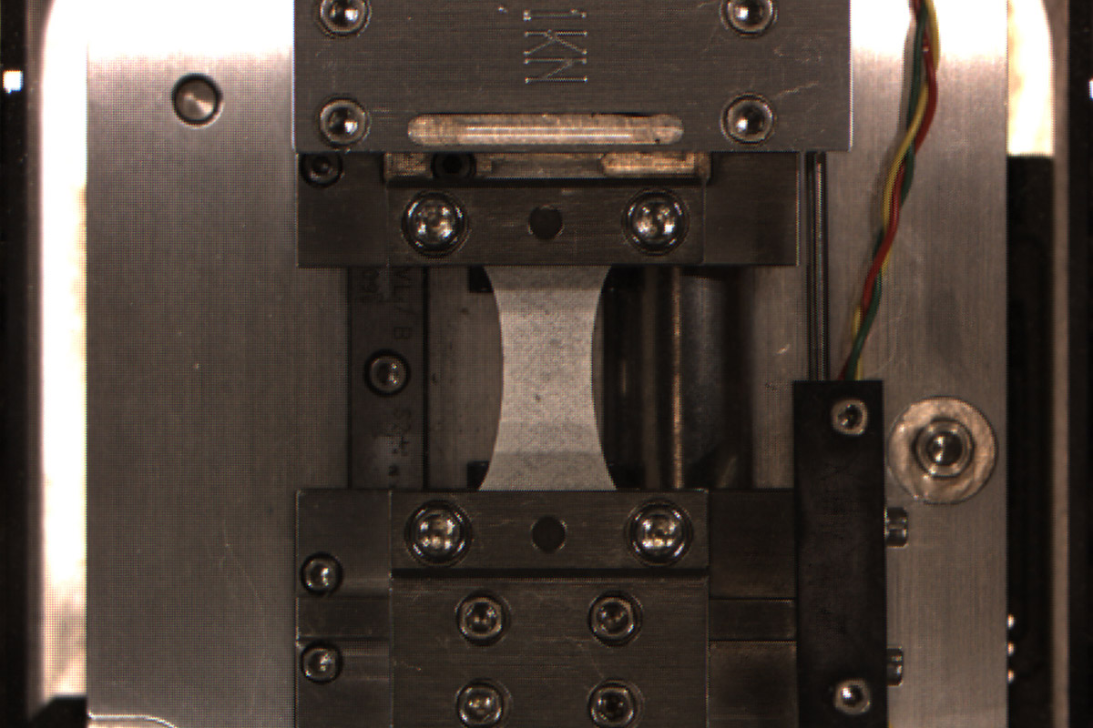
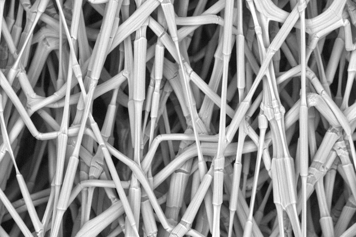
Figure 8. Images of PCL-PET electrospun fibers being tested on a tensile stage (A) and imaged using the Phenom Desktop SEM (B).
Automated Analysis of SEM Data
Manual analysis of SEM data, especially in applications where high throughput is required, can present significant challenges. Automated software, such as FiberMetric for the Phenom SEMs, enables quick, operator-independent, statistically significant data acquisition. Results from FiberMetric include tens of thousands of individual fiber diameters and orientations from across the sample. Figure 9 shows the FiberMetric user interface and examples of the output generated by the software.
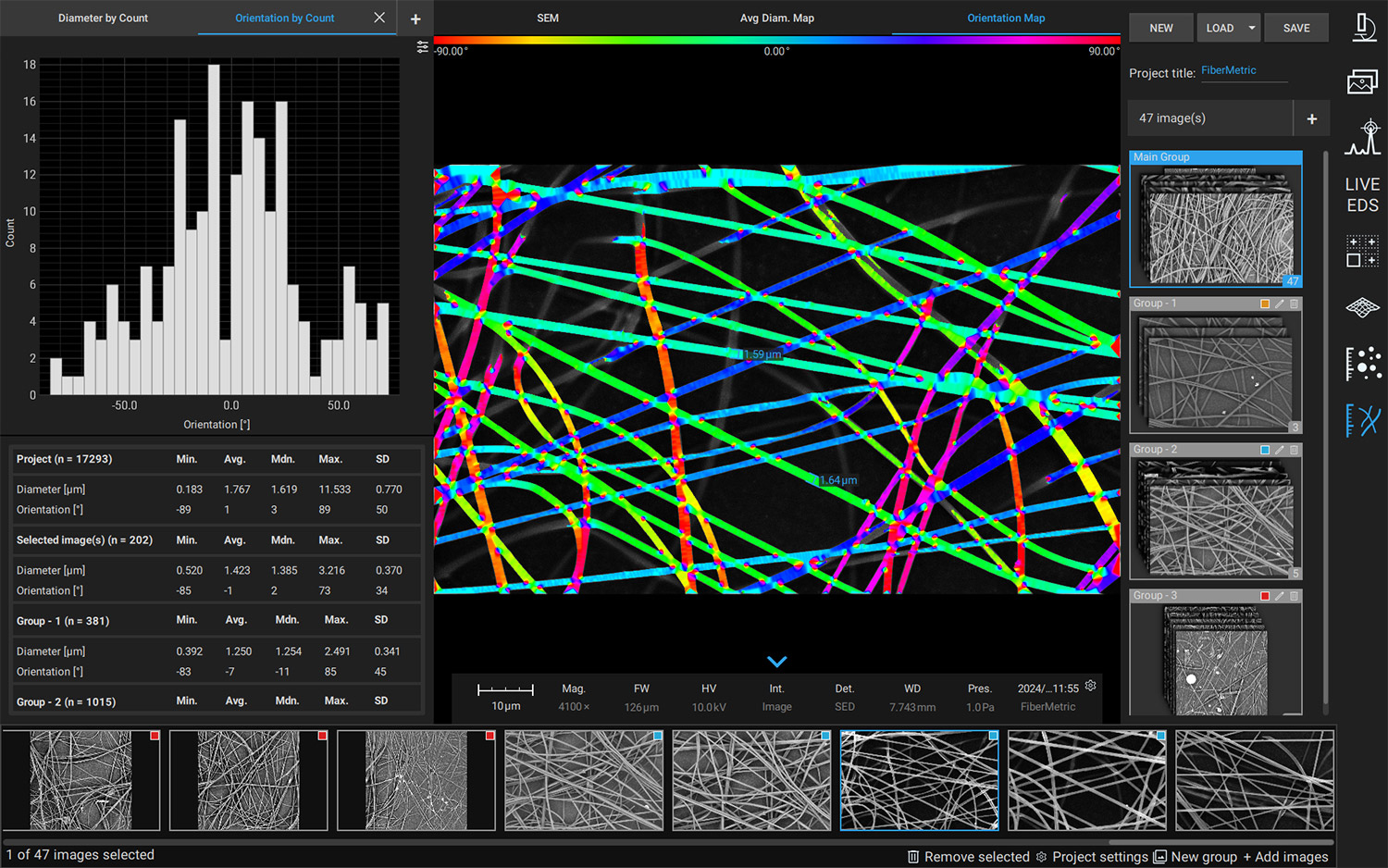
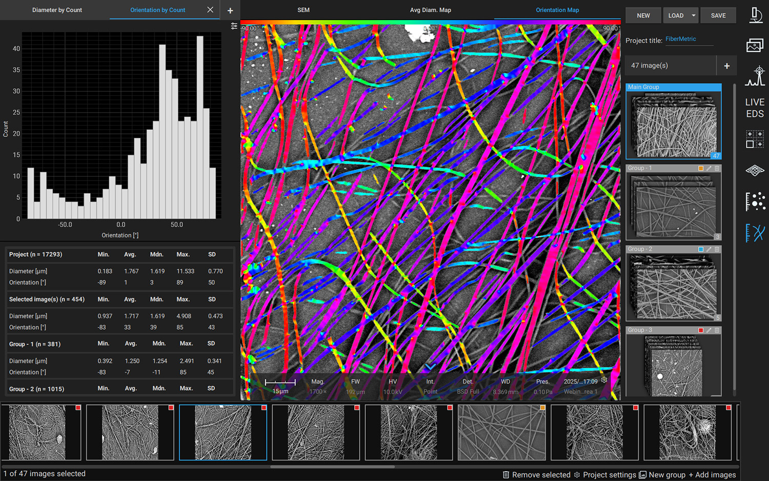
Figure 9. FiberMetric user interface for Phenom desktop SEM
Wettability Analysis
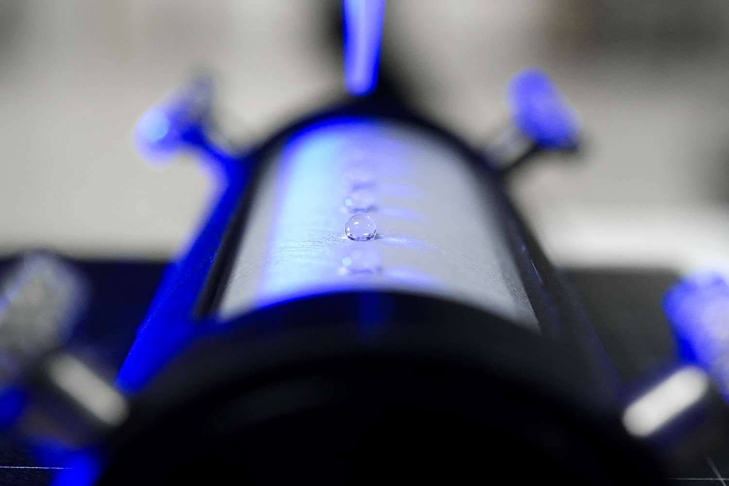
Wettability quantifies the tendency of liquids to spread across a chosen material’s surface. Optical tensiometers can characterize this property using contact angle measurements with different probe liquids. This is critical for assessing cleanliness, coating, adhesion, and other material quality factors. Advanced optical tensiometers, such as the Attension Theta Flow, can also account for surface roughness while performing these measurements. Figure 10 shows the Theta Flow optical tensiometer performing a sessile drop measurement on a curved sample surface.
Conclusion
Electrospinning has emerged as a powerful and flexible technique for the fabrication of polymer fibers with precisely tunable diameters, morphologies, and functional architectures. By carefully controlling material and solvent selection, processing parameters, and environmental conditions, researchers and manufacturers can tailor fiber properties to meet the demands of diverse applications. Equally important, advanced characterization methods such as scanning electron microscopy and optical tensiometry enable detailed evaluation of fiber structure and quality. The combination of electrospinning fabrication and rigorous characterization form the foundation for translating electrospun fiber technologies from laboratory-scale studies to reliable, scalable, and application-ready materials.
References
- Xue, J.; Wu, T.; Dai, Y.; Xia, Y. Electrospinning and Electrospun nanofibers: methods, materials, and applications. Chemical Reviews 2019, 119 (8), 5298–5415. https://doi.org/10.1021/acs.chemrev.8b00593. ↩︎
- Ji, D.; Lin, Y.; Guo, X.; Ramasubramanian, B.; Wang, R.; Radacsi, N.; Jose, R.; Qin, X.; Ramakrishna, S. Electrospinning of nanofibres. Nature Reviews Methods Primers 2024, 4 (1). https://doi.org/10.1038/s43586-023-00278-z. ↩︎
- Stachewicz, U.; Szewczyk, P. K.; Kruk, A.; Barber, A. H.; Czyrska-Filemonowicz, A. Pore shape and size dependence on cell growth into electrospun fiber scaffolds for tissue engineering: 2D and 3D analyses using SEM and FIB-SEM tomography. Materials Science and Engineering C 2017, 95, 397–408. https://doi.org/10.1016/j.msec.2017.08.076.↩︎