The nanoindentation experiments can be performed in several modes depending on the material properties desired. The ISO method is used to check the calibrations of the system while continuous stiffness measurements provide the depth-dependent properties. The viscoelastic response can be characterized by measuring the complex modulus of the material while performing frequency sweeps over the desired range. The fatigue testing can be performed in the cyclic indentation mode to measure the fatigue/fracture life of materials.
3D and 4D maps provide an excellent way to characterize the surfaces of heterogeneous materials. It is also useful when a large data set is needed for the statistical analysis of materials. The thin film properties are measured by our advanced analytical solutions to remove the substrate effect in the data. The scratch resistance and adhesive force measurements enable users to perform various analyses in many research, industrial and educational settings.
How does a Nanoindenter work?
Nanoindentation is the latest technology that enables researchers to measure mechanical properties such as modulus and hardness of materials in different shapes, sizes and scales. Most notably, this technique does not need any sample preparation and can measure properties for various materials ranging from hard superalloys to soft biomaterials within seconds making it the fastest technique for such measurements. It is a significant development over regular uniaxial tensile and shear testing methods that take days from samples preparation to final results.
Nanoindentation is used in universities and industries to characterize thin films in electronics and packaging products, advances alloys for cutting tools, coatings for thermal barriers, viscoelastic properties of polymers, microhardness in industrial quality and control, scratch and wear resistance and many more. The basic measurements needed to perform nanoindentation are Load and depth during the experiments. The indenters of different geometries such as Berkovich for E and H, spherical for stress-strain, flat punch for complex modulus, cube corner for fracture toughness, spherical cone for scratch measurements, wedge for 3 point bending can be used to measure the properties a user is interested in.
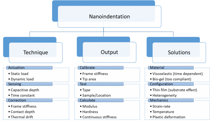
A pictorial summary of the nanoindentation process is given in the figure below which points out all the necessary steps needed and performed during the nanoindentation process. The technique involves an actuation process to apply a load, sensing the displacements and then applying the corrections needed. The output is the raw data which is calibrated for the frame stiffness, the tests are performed on the specified sites with micrometer spatial distribution and the properties are subsequently calculated. The solutions are divided based on the type of material to give elastic, viscoelastic and soft material properties. Configuration dependent properties for thin films, heterogeneous alloys/composites, layered materials, irradiated/heat treated zones can be calculated as well. The nanoindentation also provides rate dependent, temperature dependent and plasticity dependent such as fracture toughness measurements. This makes nanoindentation the most versatile tool available for the mechanical characterization of materials.
After pointing out many advantages of this technique, the next question that needs to be answered is how nanoindentation works. The success of this technique depends on the understanding of contact mechanics and availability of advanced data acquisition tools. The basic idea is that when we probe a material with a very small probe/indenter, the material properties can be predicted based on the interaction of the probe with the material. The physics behind this goes back to 1800’s when Hertz, Sneddon and many other researchers developed the necessary contact mechanics for two-body contact but it was not until 1990’s when Oliver and Pharr took it a step further and found a way to measure the modulus and hardness of a material based on its contact with another known material. In the most commonly used indenters, that known material is diamond.
The diamond probe with a tip as small as 100 nm is used to indent the surface of a sample. The load applied to the tip and the depth of penetration is subsequently measured during the process. The indentation depth is used to calculate the area of the tip that was in contact during the indentation. This area is used to measure the hardness of the material.
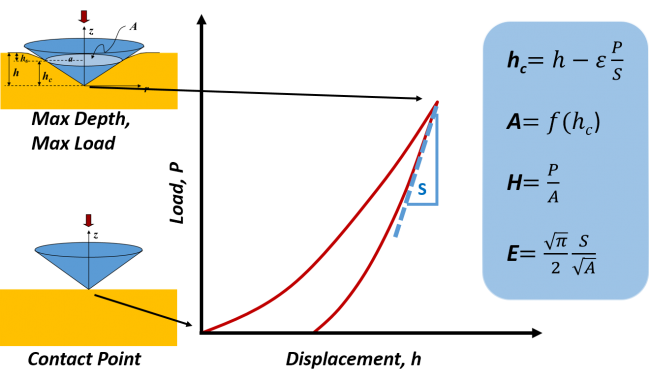
On the other hand, unloading portion of the load-depth data contains the information of the stiffness of the material being tested. It is related to the contact area. Once we know the stiffness and contact area, we can calculate the reduced modulus of the system.
Continuous Stiffness Measurement
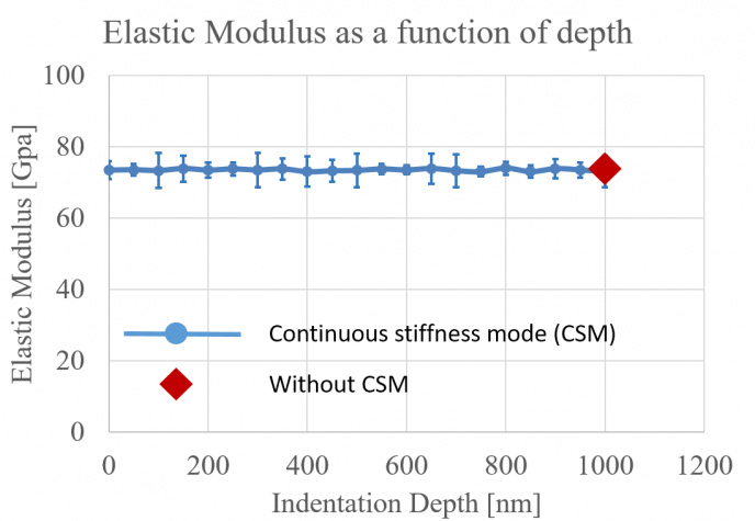
In conventional quasi-static indentation testing, the stiffness of contact is determined by analyzing the force vs. displacement curve during unloading. This depth-sensing method provides a single measurement for the given indentation depth.
The Continuous stiffness measurement (CSM) technique is a revolutionary step in the mechanical property measurement of materials. It allows the measurement of depth-dependent properties of materials in a single step. The method involves applying a dynamic load on the top of the static load while loading. The dynamic part of the load is then used to measure the stiffness which is further processed to calculate the modulus and hardness of the material.
The CSM method offers a means of separating the in-phase and out-of-phase components of the load-displacement history. The separation provides an accurate measurement of the location of initial surface contact and continuous measurement of contact stiffness as a function of depth or frequency, thus eliminating the need for unloading cycles. This makes continuous stiffness measurement a powerful tool not only for stiff materials such as metals, alloys, and ceramics but also for time-dependent materials like polymers, structural composites, and biomedical materials. Indentation tests using CSM can be controlled with a constant strain rate, a critical test parameter for material systems such as pure metals or low-melting-point alloys, and polymer films and film/substrate systems.
High Temperature Nanoindentation
It is difficult to maintain temperature without thermal drifts in a high-temperature experiment. When time or temperature dependent deformation occurs, it becomes difficult to decouple creep and elastic recovery during the unloading segment of a quasi-static test for the calculation of stiffness. So, as opposed to measuring the stiffness from unloading the material, the CSM technique imposes harmonic displacement oscillation during the hold period at peak indentation force to measure high-temperature properties.
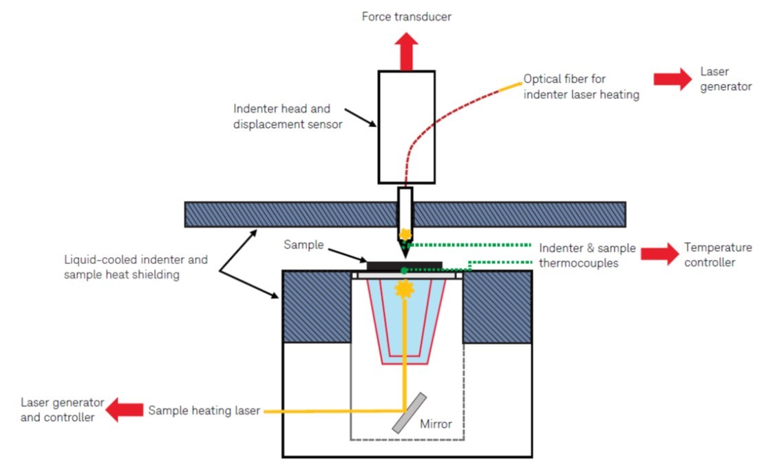
High-temperature nanoindentation allows for controlled temperatures and the ability to test samples under dynamic temperature conditions. A laser-heated indenter tip prevents disturbance of substrate temperature during measurement. Exceptional precision on continous stiffness measurements can be achieved by keeping the tip and sample at the same temperature.
Traditional Tests
Material testing is one of the most important steps in new material development as well as product development. Nanoindentation is now the most versatile and preferred method of performing experiments to measure properties such as modulus, hardness, fracture toughness etc.
Over the last century, various experiments had been in practice such as uniaxial tests to measure elastic modulus and tensile strength, shear tests to measure the shear strength and crack propagation tests to measure the fracture toughness. All these tests need elaborate sample preparation and are time-consuming. The basic description of these tests is given below.
Uniaxial Tensile Tests
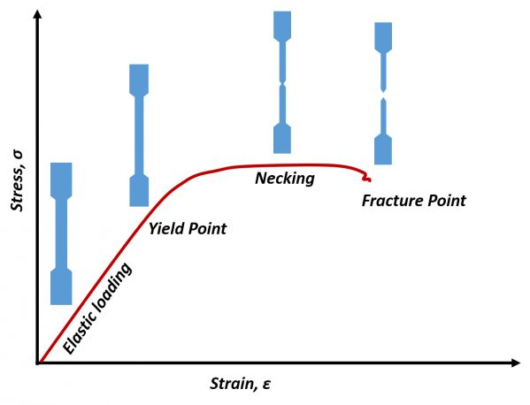
The uniaxial tensile tests are performed to measure elastic modulus and ultimate tensile strength of materials. The test specimens are dog bone shaped as per the ASTM E8 standards. The tests are performed in displacement controlled manner with the load being monitored by load cells. As the loading continues, the specimen starts to deform elastically followed by plastic deformation which then starts necking and ultimately fails by fracturing.
The strain during the test is calculated as the change in the gauge length divided by the original length.
ε = ΔL/L0
Calculation for strain.
The stress is calculated as the load divided by the cross-section area of the specimen.
σ=F/A
Stress calculation.
Shear Tests
The shear tests are applied using the same loading principles as the uniaxial tension tests but with modified loading grips that transforms the load in the shear direction. There are multiple ways to apply these kinds of loads. The specimens are prepared according to ASTM standards and loaded in either displacement controlled or force controlled mode. The shear modulus and shear strength of the material are measured from these tests.
As the loading continues, the specimen starts to deform elastically followed by plastic deformation in shear direction which then starts cracking and ultimately fails by fracturing.

Fracture Tests
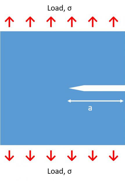
The fracture toughness of a material is measured by crack propagation tests. The sample is prepared as per ASTM standards with a pre-crack in it. The sample is loaded in the lateral direction of the crack. As the crack propagates, both the load and the crack propagation speed is monitored which is further used to find the fracture toughness of the material.
In general terms, fracture toughness is the resistance of the material to the propagation of the crack. A crack could propagate in three modes: Mode I – tensile mode, when the stress is perpendicular to the crack, Mode 2 – shear mode, when the applied stress is in shear direction (in-plane shear), Mode 3 – tear mode, when the applied stress is in twist direction (out of plane shear).
The stress at the crack tip is defined by a term called stress intensity factor defined as:
KI = σ√πa
Calculation of the stress intensity factor.
The stress intensity factor at which crack starts to propagate is called the critical stress intensity factor which is equivalent to the fracture toughness of the material.