Profilometry is a technique used to extract topographical data from a surface. This can be a single point, a line scan or even a full three dimensional scan. The purpose of profilometry is to get surface morphology, step heights and surface roughness. This can be done using a physical probe or by using light.
Metrology is the science of measurement. How rough is the sample? How high are the features? How much of the area has voids or particles? What is the defect density? Answers to these questions are often quantified using profilometry.
How a Profilometer Works
All profilometers consist of at least two parts – a detector and a sample stage. The detector is what determines where the points on the sample are and the sample stage is what holds the sample. In some systems, the sample stage moves to allow for measurement, in others the detector moves and in some both move.
There are two types of profilometers: stylus vs optical. Stylus profilometers use a probe to detect the surface, physically moving a probe along the surface in order to acquire the surface height. This is done mechanically with a feedback loop that monitors the force from the sample pushing up against the probe as it scans along the surface. A feedback system is used to keep the arm with a specific amount of torque on it, known as the ‘setpoint’. The changes in the Z position of the arm holder can then be used to reconstruct the surface.
Stylus Profilometry
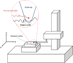
Stylus profilometers use a probe to detect the surface, physically moving a probe along the surface in order to acquire the surface height. This is done mechanically with a feedback loop that monitors the force from the sample pushing up against the probe as it scans along the surface. A feedback system is used to keep the arm with a specific amount of torque on it, known as the ‘setpoint’. The changes in the Z position of the arm holder can then be used to reconstruct the surface.
Stylus profilometry requires force feedback and physically touching the surface, so while it is extremely sensitive and provides high Z resolution, it is sensitive to soft surfaces and the probe can become contaminated by the surface. This technique can also be destructive to some surfaces.
Because a stylus profilometer involves physical movements in X, Y and Z while maintaining contact with the surface, it is slower than non-contact techniques. The stylus tip size and shape can influence the measurements and limit the lateral resolution.
Schematic of a stylus profilometer
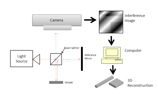
Schematic of an Interferometric profilometer
Optical Profilometry
Optical profilometry uses light instead of a physical probe. This can be done a number of ways. The key component to this technique is directing the light in a way that it can detect the surface in 3D. Examples include optical interference, using a confocal aperture, focus and phase detection, and projecting a pattern onto the optical image.
Confocal Profilometry
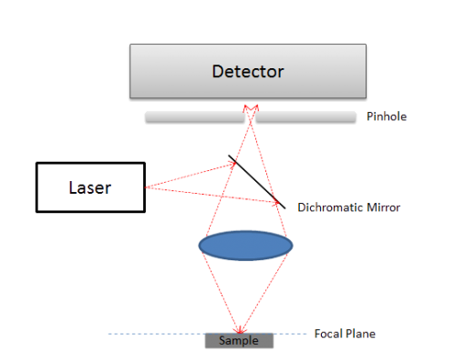
Schematic of confocal profilometry.
Confocal profilometry is a point scanning optical technique used to image the sample surface. It works by using a small aperture, known as a confocal aperture. Highly focused light is projected through the aperture and only surfaces within the focal plane will provide a useful signal. The optics are scanned up and down above the surface until a bright spot is observed. Once a bright spot is observed the instrument calculates the distance to that point on the surface, giving it a point in Z. The optics then scan along the surface laterally while maintaining a bright spot to reconstruct the surface.
Grid Confocal
Pattern Projection with Focus Detection
Typically, software used on optical instruments can have difficulties determining what is in focus and what is out of focus. The accuracy of the optics may limit how effectively the focal plane can be resolved.
By using advanced optics to project a sharp pattern that will only be in focus at a precise distance, the software and optics are able to determine what is in the focal plane more easily and with greater accuracy. This also allows for more flexibility in measuring transparent samples as the projection will only be in focus on a real surface.
This combination technique is slightly more complicated than focus detection but it provides more accurate measurements and simpler software detection.
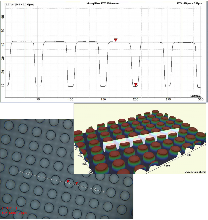
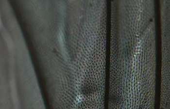
Micropillars for self-cleaning surfaces analyzed using Zeta 3D optical profiler.
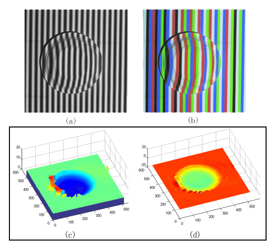
Schematic and images for pattern projection profilometry.
Pattern Projection
Pattern projection profilometry works by projecting a known pattern onto the sample and comparing what is projected to what is reflected by the sample. By comparing these two the surface of the sample can be reconstructed by software.
Focus Detection
Focus detection works much like how we see the world. The instrument determines what is in focus and what is out of focus by looking for sharp contrasts. Areas with sharp contrast are deemed in focus, and by knowing this focal length of the optics you can determine the distance. This generally works by scanning the optics in the Z direction and using the camera in order to create a three-dimensional volume of data. After the data is acquired, the parts that are out of focus are cut out and you are left with a representation of the surface of the sample.
This technique can also be performed by using a zoom microscope with a variable focus to create the volume. This technique is generally simpler with less resolution at a lower cost. By using regular microscope objectives and precision Z movements, the X, Y and Z resolution can be greatly enhanced; the resolution is still lower than confocal or interferometry instruments.