Controlling the Orientation of Electrospun Nanofibers for Tissue Engineering

Introduction

Electrospinning is a versatile and promising technique for fabricating nanofibrous scaffolds that can biomimic the extracellular matrix (ECM) of natural tissues. These nanofibrous scaffolds have several unique properties, including a high surface area-to-volume ratio, adjustable pore size, and tunable mechanical and biochemical properties. The mechanical properties of fiber scaffolds can be easily tailored by adjusting the fiber diameter, density, orientation, and polymer composition. This can allow for the creation of scaffolds with a range of mechanical properties that mimic natural tissues’ properties.

A few of the applications of electrospinning for tissue engineering include use as wound dressings to promote rapid healing, scaffolds to mimic the properties of natural bone tissue to promote bone regeneration and repair, and scaffolds to engineer cartilage tissue, skin, and vascular tissue. Electrospinning is a highly promising technique for tissue engineering applications and has the potential to revolutionize the field of regenerative medicine and biotextiles.

Random vs Aligned Fibers

The alignment of electrospun nanofibers can play an important role in tissue engineering applications. The orientation of the fibers can impact the mechanical, and biological properties of the scaffold, and ultimately affect its ability to support cell attachment, proliferation, and differentiation. The two main orientations obtained during electrospinning are aligned (Figure 1a) and random (Figure 1b) fibers. While random fibers are randomly oriented at different angles throughout the collected sample, aligned fibers are typically oriented in the same direction.

Aligned fibers can provide directional cues for cells, guiding their orientation, proliferation, and organization within the scaffold. This can be particularly important for tissues such as muscles, nerves, and the outer layer of saphenous veins, which require aligned structures for proper function. Neural cells have much better mobility and proliferation on aligned electrospun structures. In the case of vascular grafts, aligned fibers at the outermost layer and surrounding the circumferential axis enhance the mechanical properties by improving burst pressure resistance.

Figure 1. Electrospun polyacrylonitrile (PAN) nanofibers with different orientations: a) aligned and b) random.

Random fiber orientation is advantageous for tissue engineering and medical devices as it offers increased surface area which facilitates cell adhesion, proliferation, promotes tissue regeneration, and nutrient exchange (typically 100 µm before vascularization). When pore sizes are large enough, random orientation fibers allow cell infiltration throughout the scaffold which helps with nutrient and oxygen exchange and waste removal. Random fibers can be used for tissues without specific orientation, such as skin or adipose tissue.

Rotating Drum Collector

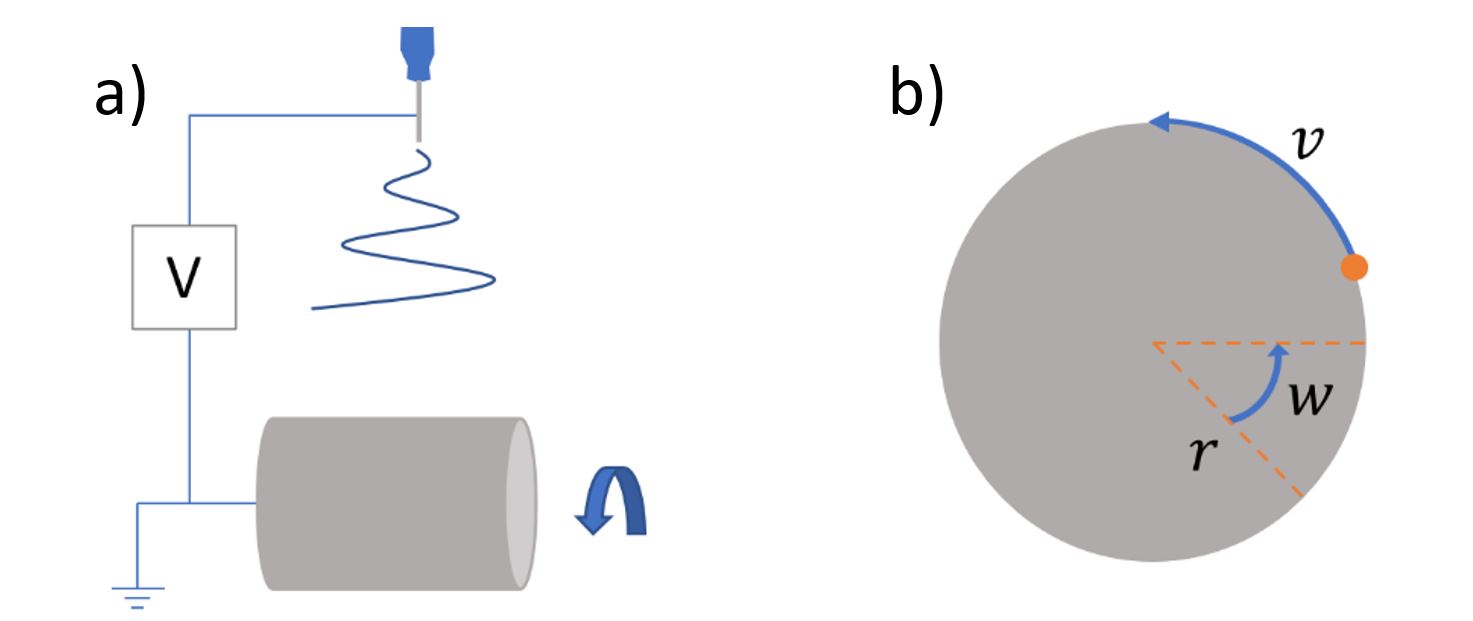
The most efficient, and increasingly common method of collecting aligned fibers is by using a rotating drum collector (Figure 2a). To achieve your desired fiber orientation, the key parameters to optimize during fiber collection are the diameter of the rotating drum collector, and the drum’s speed. The degree of fiber alignment is determined by the linear speed of the rotating collector. As linear speed increases, fibers become more aligned. Linear speed on a rotating collector is calculated by r×w, where v = linear velocity, r = radius of drum collector, and w = angular velocity (Figure 2b). A rotating drum with a 10 cm diameter operating at 500, 1,000, and 2,000 rpm will generate a linear speed of 2.62, 5.24, and 10.47 m s-1, respectively. A 20 cm drum will achieve these same linear speeds at half the rpm.
Figure 2. a) Schematic diagram illustrating basic electrospinning setup to obtain random or aligned nanofibers. b) Diagram with variables to consider when calculating linear velocity (v) on a circular rotating collector with radius, r , and angular velocity, w .

To fabricate aligned fibers, the linear speed of a rotating drum must be increased which could cause air turbulence. This in turn can affect fiber orientation during sample collection. To counteract this, electrospinning equipment is often designed so an opposite charge can be applied to the collector. This improves the electric field between the needle tip and the collector, which mitigates turbulence issues allowing the collection of aligned fibers after optimization.

Figure 3. The Spinbox electrospinning system.

Spinbox

The Spinbox is an entry-level, modular, benchtop electrospinning and electrospraying system with a wide range of capabilities and reliability to enable researchers to develop their concepts and prototypes. Spinbox’s assortment of accessories and safety features, make it effective for labs looking to upgrade from home-built systems to industrial companies wanting to explore scalable new ideas. The Spinbox not only offers the basic essential features to fabricate nanofibers but also includes a chemically resistant cabinet and capabilities to generate aligned fibers and core-shell fibers. It also includes a Taylor cone camera and T/RH sensor to monitor process stability. A flat plate comes as a standard collector and a rotating drum platform is among the available options.

Effect of Linear Velocity on Fiber Orientation

To demonstrate the effects of changes in linear velocity on fiber alignment, a 10 cm drum collector was used on a Spinbox to collect electrospun polycaprolactone (PCL). PCL was selected for this example due to its extensive use in tissue engineering and drug delivery applications. The rotating speed was varied while all other electrospinning conditions were kept constant. When the drum was set to 500 rpm, the collected fibers had random orientation with an average diameter of 3.44 µm (Figure 4a). As rotational speed was increased to 1,000 rpm (Figure 4b) and 1,500 rpm (Figure 4c), a transition towards aligned fibers was observed and fiber diameter only changed marginally. At 2,000 rpm (Figure 4d) the high linear speed stretched the fibers into alignment and reduced the fiber diameter to 2.75 µm.

Figure 4. Microstructure of electrospun PCL collected onto a 10 cm rotating drum at different speeds using the Spinbox technology: a) at 500 rpm (v = 2.62 m s-1), b) at 1,000 rpm (v = 5.24 m s-1), c) at 1,500 rpm (v = 7.85 m s-1), and d) at 2,000 rpm (v = 10.47 m s-1). Fiber diameter (FD) is reported as average ± standard deviation for each condition. Scale bar = 50 µm. Images were collected with the Phenom Desktop Scanning Electron Microscope (SEM).
Figure 5. Fiber orientation analysis (n=750) from electrospun PCL collected at different rotating speeds using a 10 cm diameter drum: a) at 500 rpm (v = 2.62 m s-1), b) at 1,000 rpm (v = 5.24 m s-1), c) at 1,500 rpm (v = 7.85 m s-1), and d) at 2,000 rpm (v = 10.47 m s-1).

 Figure 5 shows the quantitative analysis for fiber orientation on all PCL electrospun samples from Figure 4. Parameters for the analysis were: a distribution of 0 to 180°, a bin size of 5°, and 750 measurements performed per sample. As expected from Figure 4a, when the rotational speed was only 500 rpm (Figure 5a), fibers did not have enough linear speed to stretch into an aligned orientation. This resulted in an average frequency of aligned fibers below 40 across the sample. When the speed slowly increased to 1,000 rpm (Figure 5b) and 1,500 rpm (Figure 5c), fiber orientation gradually shifted towards 90°. At 2,000 rpm (Figure 5d) there was a much tighter distribution of aligned orientations between 85° and 95°, reaching a peak frequency of 160.

Conclusion

To achieve desired fiber orientation when using the Spinbox system, the key parameters to optimize during sample deposition are the diameter of the rotating drum collector, the drum’s linear speed, and the electrical bias. Whether you are fabricating randomly oriented fibers or aligned fibers, Spinbox systems simplify the workflow and provide batch-to-batch reproducibility.

Although this note demonstrates the Spinbox for fabricating aligned fibers, similar results can be obtained from the Fluidnatek LE-50 as the drum dimensions are the same. Similar protocols have also been developed for more advanced systems such as the Fluidnatek LE-100 and LE-500 platforms where super-aligned electrospun fibers can be obtained.

Download the Tech note:

Hidden

Admin Calculation Fields

Hidden
Hidden
Hidden
Hidden
Hidden
Name(Required)

Questions about this tech note? Send us a message!

This site is protected by reCAPTCHA and the Google Privacy Policy and Terms of Service apply.