Introduction
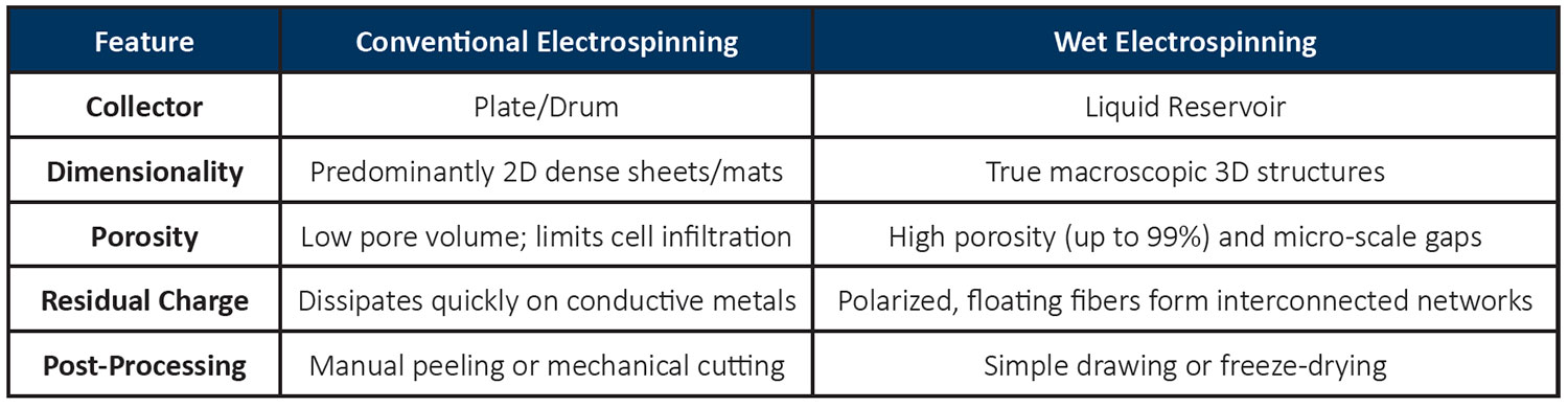
Conventional electrospinning is widely used to fabricate nanofibrous materials with high surface-area-to-volume ratios and tunable fiber diameters. However, the process typically produces densely packed, two-dimensional (2D) nonwoven mats. In conventional setups, fibers are collected on a solid conductive substrate, such as a flat stainless-steel plate or rotating drum.1, 2, 3, 4, 5, 6 As successive layers of fibers accumulate, they pack tightly on top of one another, forming a compact structure with relatively small pore sizes. Although these structures are suitable for applications such as fabricating ultrathin membranes, medical device coatings, and filtration sheets, their limited porosity and thickness can restrict cell infiltration, tissue ingrowth, and fluid permeability.
To overcome these limitations, researchers have explored methods to transform conventional 2D electrospun mats into three-dimensional (3D) porous structures. One approach involves post-processing the electrospun mat through chemical expansion using hydrogen gas generated by reacting sodium borohydride with water.7 This process expands the fiber network into a more open, sponge-like structure. However, successful expansion requires the fibers to be completely dry and free from fiber-fiber bonding. Wet electrospinning offers a simpler, one-step alternative for fabricating 3D nanofiber structures. Instead of collecting fibers on a solid metal substrate, the electrospun fibers are deposited directly into a grounded liquid bath. The liquid collection medium prevents the fibers from accumulating as a densely packed 2D mat, allowing them to assemble into a highly porous, interconnected, sponge-like structure. This approach enables the direct fabrication of macroscopic 3D nanofiber architecture without requiring a separate expansion step, offering new opportunities for developing porous scaffolds, tissue engineering materials, and other applications where high porosity and interconnected pore networks are essential.
How Does Wet Electrospinning Generate 3D Nanofiber Structures?
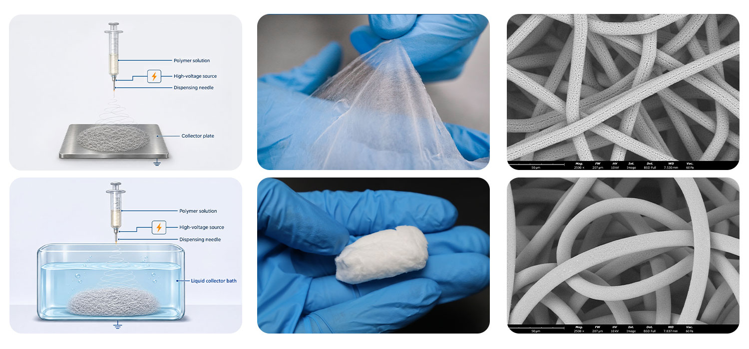
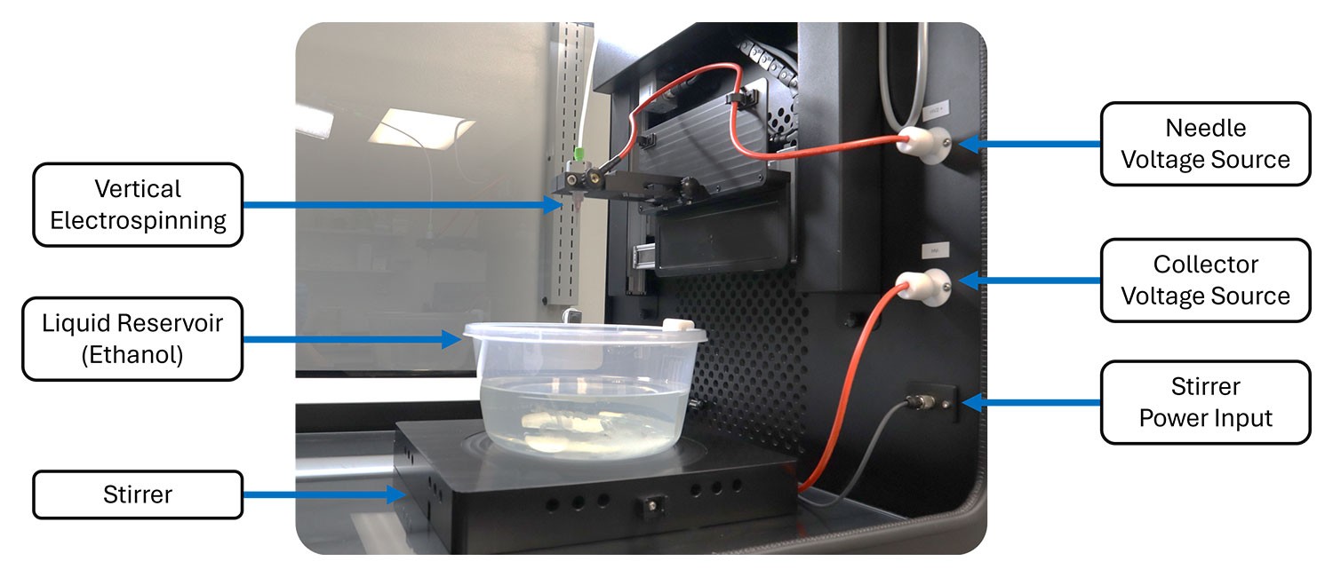
In conventional electrospinning, fibers are deposited onto a grounded solid collector, such as a metal plate or rotating drum. In wet electrospinning, the solid collector is replaced with a grounded liquid reservoir (Figure 2). As fibers enter the liquid, they disperse and form a loosely interconnected network with increased looping and tortuosity. The liquid medium helps minimize fiber-fiber bonding and allows the fibers to assemble into an open, porous structure. Fiber deposition and aggregation are also influenced by the gradual dissipation of electrical charge, as well as the liquid’s density and surface tension. Together, these effects promote the formation of macroscopic, sponge-like 3D nanofiber structures.8
The collection liquid plays an important role in determining the resulting fiber architecture. Key properties of the collection liquid that should be considered include the solubility of the polymer and incorporated additives, surface tension that promotes fiber wetting and penetration into the liquid rather than accumulation at the liquid surface (ex. ethanol and/or isopropyl alcohol), and density of the liquid that is lower than, or comparable to, that of the polymer to help facilitate fiber migration into the reservoir. By combining a suitable liquid collection medium with controlled electrospinning conditions, researchers can produce highly porous 3D nanofiber structures in a single processing step.
Applications for 3D Nanofibrous structures
Three-dimensional (3D) nanofibrous structures offer unique material properties that extend the applications of 2D electrospun membranes and mats. Their high porosity, interconnected pore networks, large surface-area-to-volume ratios, and tunable architecture make them attractive for applications requiring enhanced permeability, cell infiltration, and mass transport. By enabling the fabrication of thicker, highly porous fiber networks, 3D nanofibrous structures provide new opportunities to develop materials that more closely replicate the architecture and functionality of natural tissues.
- Tissue Engineering: Conventional 2D electrospun mats can mimic the extracellular matrix (ECM) through controlled fiber diameter and composition. However, their dense structure can limit cell infiltration and proliferation. In contrast, 3D nanofibrous scaffolds offer larger, interconnected pores that support deeper cell migration and provide a more tissue-like architecture. Their thickness and porosity make them particularly suitable for applications such as bone tissue engineering, where osteoblasts must penetrate the scaffold to support new bone formation. Incorporating bioceramics or osteogenic growth factors can further enhance their potential for bone regeneration. Other applications include bone grafts, cartilage repair, artificial skin substitutes, and 3D cell culture.
- Traumatic Injury and Hemostasis: Materials with super elasticity and high absorption capacity are valuable for hemostatic applications, where rapid bleeding control is essential to prevent hemorrhage following traumatic injuries. 3D electrospun structures can provide these properties by expanding within the wound while absorbing blood at levels exceeding 6,000% of their initial weight, more than twice the absorption capacity of some commercially available products.7 Furthermore, the room-temperature, one-step electrospinning process offers flexibility in material selection, enabling researchers to tailor biodegradability and incorporate hemostatic agents to meet specific application requirements.
- Minimally invasive Biological Sampling: Shape-recoverable 3D electrospun nanofiber structures integrated into swallowable capsules offer a promising approach for collecting biological specimens from internal organs, particularly the gastrointestinal tract, without requiring invasive medical procedures. After swallowing, the capsule can expand at the target location, exposing its porous nanofiber structure to surrounding biological fluids and tissue surfaces. Following sample collection, the device can be retrieved for subsequent analysis.
These devices have potential applications in microbiome research, gastrointestinal fluid analysis, and the collection of biological specimens for diagnostic testing. Unlike conventional sampling devices such as the Cytosponge, which primarily collect cells from the esophageal lining, 3D electrospun nanofiber structures can function more like highly absorbent swabs. Their large surface-area-to-volume ratio, interconnected porosity, and high absorption capacity enable the collection of not only cellular material but also bacteria, viruses, and other biological components present in surrounding fluids.9 The ability to engineer fiber composition, porosity, and mechanical properties further allows researchers to tailor these structures for specific sampling requirements, opening new possibilities for minimally invasive specimen collection and gastrointestinal diagnostics.
- Acoustic Isolation & Sound Absorption: Conventional acoustic insulation materials, such as fiberglass panels, rely on porous fiber networks to dissipate sound energy as acoustic waves travel through the material. However, their relatively large fiber diameters and spacing can limit their effectiveness in absorbing high-frequency sound waves, particularly when material thickness and weight are constrained. Three-dimensional (3D) electrospun nanofiber structures offer an alternative approach by creating highly porous networks with significantly smaller fiber diameters and interconnected pores. These structures provide a much larger fiber surface area within a given volume, increasing opportunities for acoustic wave scattering, along with viscous and thermal energy dissipation. As sound waves propagate through the complex fiber network, their energy is progressively converted into heat, reducing sound reflection and transmission. The ability to engineer fiber diameter, porosity, and scaffold thickness also allows researchers to tailor acoustic performance across different frequency ranges.
- Oil adsorption and Separation: Compared with conventional sorbents made from melt-blown polypropylene or 2D electrospun mats, 3D electrospun sponges offer a lightweight alternative with high porosity and oil absorption capacity. Studies have demonstrated that these structures can absorb up to 25 times their own weight in oil, significantly outperforming conventional sorbent materials.10 Their interconnected fiber networks provide a large accessible surface area for oil uptake, while their elastic structure allows them to be compressed to recover the absorbed oil and potentially reused or recycled. Furthermore, electrospinning enables the incorporation of hydrophobic and oleophilic properties, producing superhydrophobic and super oleophilic surfaces that repel water while selectively absorbing oil. These characteristics make 3D electrospun sponges promising materials for oil–water separation, industrial wastewater treatment, and oil spill remediation.
Safety and Environmental Considerations for Wet Electrospinning
Wet electrospinning introduces additional laboratory challenges associated with liquid handling, solvent exposure, electrical safety, and environmental control. Maintaining safe operating conditions and controlling processing parameters are essential for reproducible 3D nanofiber fabrication. Professional electrospinning systems with integrated safety features and environmental monitoring help address these challenges.
- Solvent Management and Exposure Prevention: Methanol, ethanol, isopropyl alcohol, and butyl alcohol are commonly investigated as collection liquids because of their relatively low surface tension. However, vapors from open liquid reservoirs and polymer solutions can accumulate inside the equipment chamber, creating potential exposure risks. Professional systems should provide continuous negative-pressure monitoring, solvent vapor extraction, and increased ventilation when the chamber door is open. Fluidnatek systems incorporate door-open ventilation, negative-pressure sensors, and configurable operating parameters to help efficient vapor removal and minimize solvent exposure.
- Electrical Arcing Prevention: Electrospinning involves high-voltage electrical fields, making arcing a potential safety concern, particularly when working with flammable solvents. Fluidnatek systems include integrated arcing detection that automatically shuts down the equipment when an electrical arc is detected. This feature helps protect researchers, equipment, and laboratory facilities during wet electrospinning.
- Environmental Control for Reproducible 3D Structures: Environmental conditions, particularly relative humidity, can significantly influence fiber formation and solvent evaporation. Even a 5% change in laboratory relative humidity can affect jet drying behavior. If fibers enter the liquid reservoir before sufficient solvent evaporation occurs, they may bond together, potentially producing a film-like structure instead of the desired porous 3D network. Controlling temperature, relative humidity, absolute humidity, and airflow helps maintain consistent processing conditions and fiber morphology. Fluidnatek’s Environmental Control Unit (ECU) provides comprehensive environmental management to improve process reproducibility throughout the year. These capabilities are particularly valuable when optimizing polymer formulations, developing new 3D architectures, and validating processes for commercial production.
PCL Processing Using Dichloromethane (DCM)
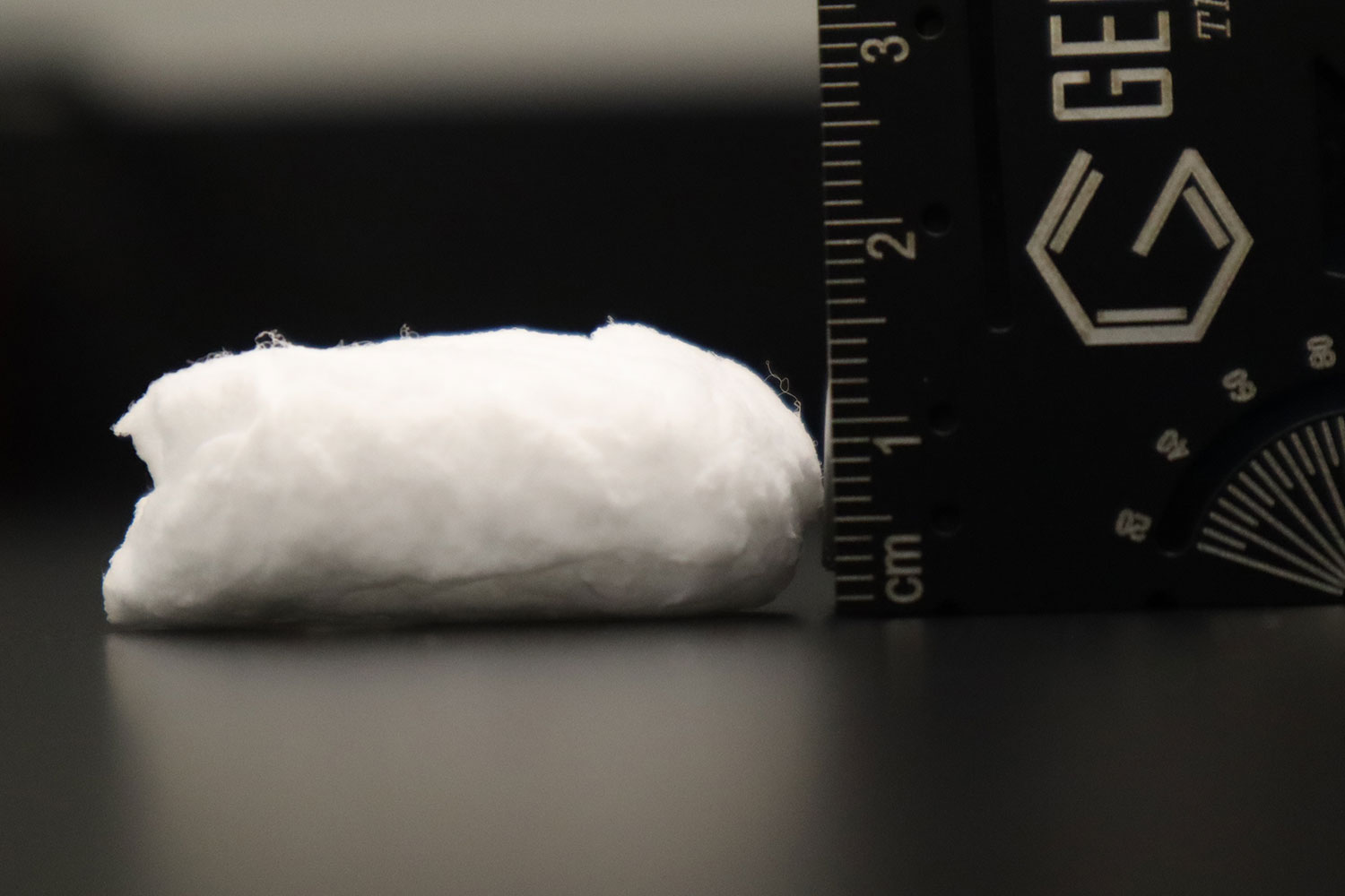
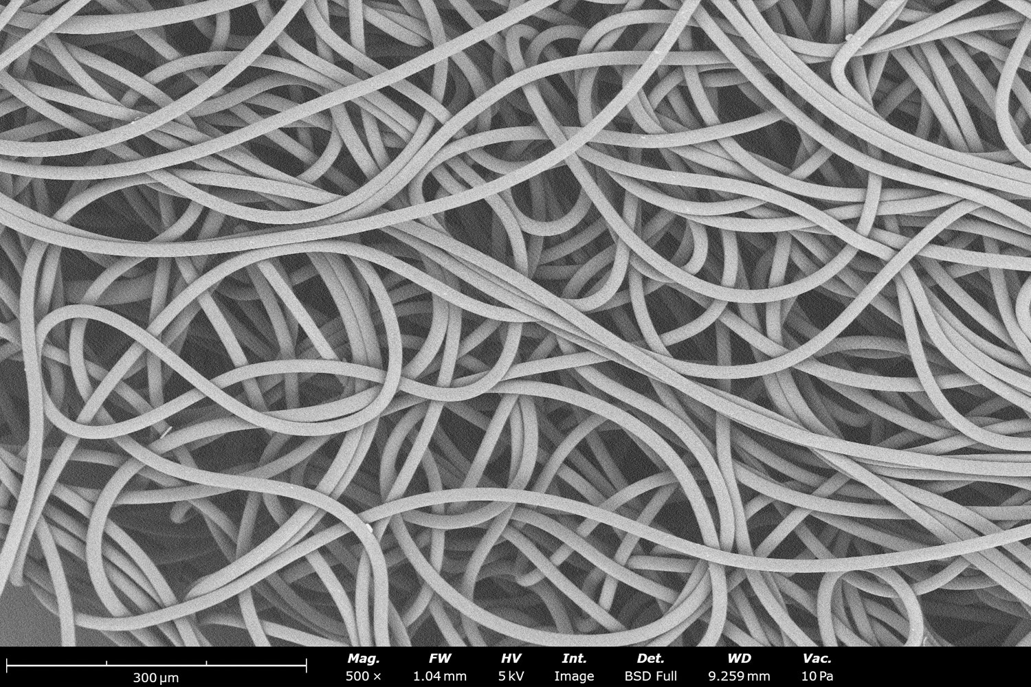
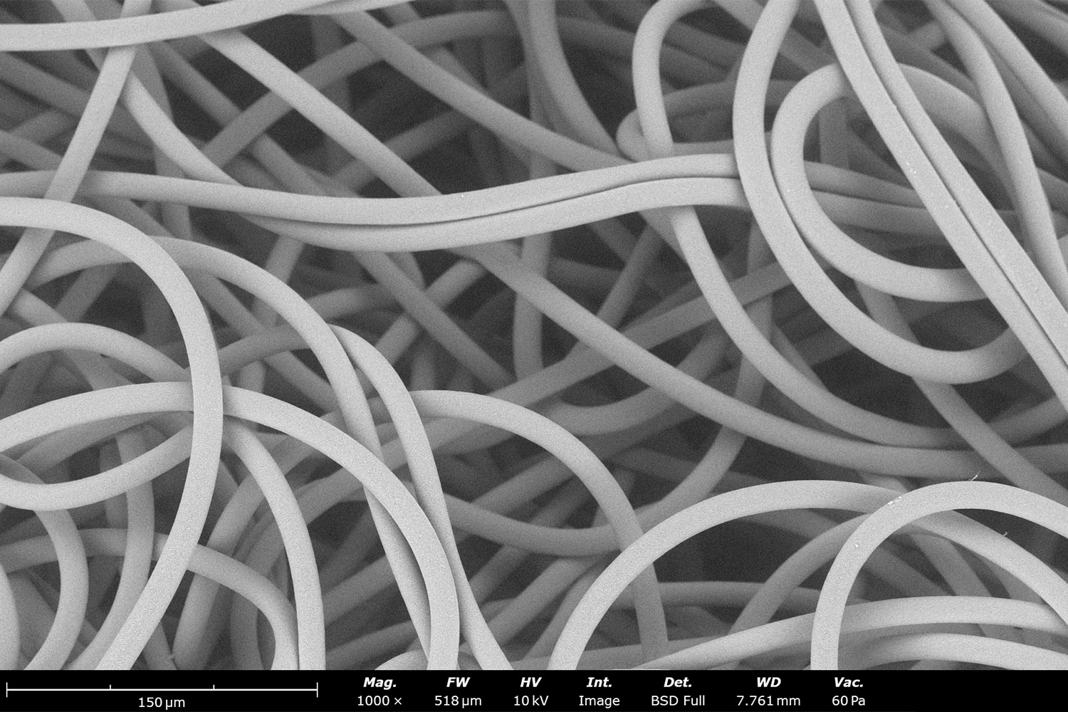
Figure 3. Wet electrospinning of 12 wt% polycaprolactone in dichloromethane. (A) Electrospun microfibers collected in the ethanol reservoir form a cotton-like 3D structure. Microstructural analysis using a Phenom Desktop SEM at a magnification of 500X (B) and 1,000X (C) reveal a network of uniform fibers.
Unlike conventional 2D electrospun mats, microstructural analysis reveals a network of relatively uniform microfibers with highly interconnected pores. The fibers also exhibit a more relaxed, coiled morphology, contributing to the formation of the porous 3D architecture. These structural characteristics are particularly attractive for tissue engineering scaffolds that require interconnected pores to support deeper cell infiltration and migration.
PCL Processing Using Hexafluoroisopropanol (HFIP)
The second example uses a 10 wt% PCL solution in hexafluoroisopropanol, processed using the same Fluidnatek LE-50 configuration and ethanol collection reservoir. The videos demonstrate how PCL microfibers progressively accumulate in the liquid bath within the first few minutes of electrospinning (Figure 4A). In some cases, gentle stirring with a magnetic stir bar can help promote fiber entanglement and facilitate the formation of the macroscopic 3D structure. The Fluidnatek system supports this capability through its liquid collector configuration.
Microstructural analysis again reveals coiled fibers and larger interconnected pores compared with conventional 2D electrospun mats (Figure 4B). However, the choice of solvent influences the resulting fiber morphology. Compared with HFIP, DCM evaporates more rapidly, which directly contributes to differences in fiber formation and results in larger fiber diameters.11 In contrast, HFIP-based processing produces smaller-diameter fibers, consistent with previously reported results.12
Together, these examples demonstrate how wet electrospinning can produce 3D PCL structures using different solvent systems, while illustrating how solvent selection influences fiber morphology, pore architecture, and the resulting scaffold structure.
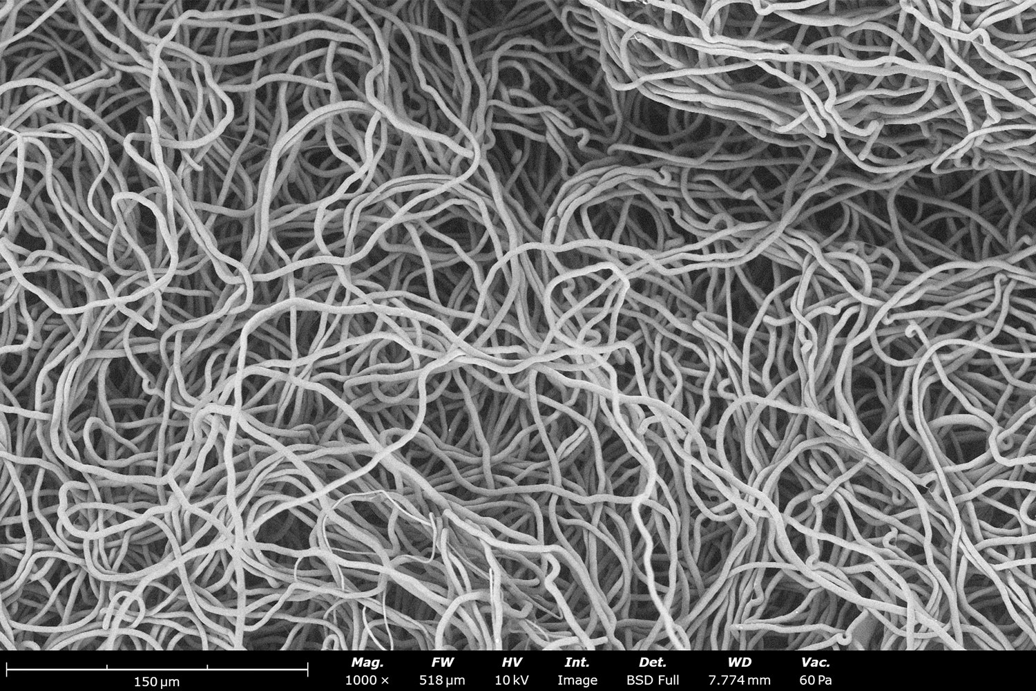
Figure 4. Wet electrospinning of 10 wt% polycaprolactone in 1,1,1,3,3,3-hexafluoroisopropanol. (A) The video shows the accumulation of PCL fibers in the ethanol reservoir. Microstructural analysis using a Phenom Desktop SEM at a magnification of 500X (B) reveal coiled fibers with large interconnected pores.
Conclusion
Wet electrospinning offers a straightforward, one-step approach to fabricating highly porous 3D nanofiber structures that overcome some of the limitations of conventional 2D electrospun mats. As demonstrated by processing polycaprolactone using two different solvent systems and collecting the fibers in an ethanol reservoir, this technique can readily produce sponge-like structures with high porosity. These architectures offer new opportunities for applications where enhanced cell infiltration, interconnected pore networks, and greater scaffold thickness are essential, including tissue engineering, regenerative medicine, and controlled drug delivery.
However, replacing conventional metal collectors with liquid reservoirs introduces additional safety considerations, particularly when working with volatile and flammable solvents. Selecting a well-designed electrospinning system with integrated safety features and precise environmental controls is therefore essential for reliable, reproducible, and safe 3D nanofiber fabrication.
References
- Marquez, J. D., Dominguez, C. I., Eades, C. B., Sumerlin, B. S., & Evans, A. M. (2026). Electrospinning of ultra-high molecular weight polymers into aligned nanofibers and their application in chemical separations. RSC Applied Polymers, 4(5), 1509–1517 https://doi.org/10.1039/d6lp00187d ↩︎
- Zhu, W., Rui, G., Chen, Y., Li, B., Zhang, S., Mather, P. T., & Zhang, Q. M. (2025). High crystallinity and polar-phase content in electrospun P(VDF-TrFE) nanofibers with low molecular weight. Journal of Applied Physics, 137(19), 194102. https://doi.org/10.1063/5.0267697 ↩︎
- Kevin K. Crown, Sean M. Kinahan, Gabriel A. Lucero, Eric C. Carnes, Yury E. Salkovskiy, Aleksandr Fadeev & Joshua L. Santarpia (2026) Water-soluble aerosol collection medium for environmental bioaerosol collections, Aerosol Science and Technology, 60:9, 982-992, https://doi.org/10.1080/02786826.2026.2636033 ↩︎
- Abdullahi, A., Moriam, K., Jiru, M., Hogan, C., Ghann, W., & Uddin, J. (2026). Electrospun PVDF nanofiber mats embedded with silver nanocubes for antibacterial wound dressing. ACS Applied Nano Materials, 9(23), 10522–10533. https://doi.org/10.1021/acsanm.6c00051 ↩︎
- Bryan, A. E., Krutko, M., Rebholz, S., Marquez, L. E., Busch, E., Dong, K., Pixley, S. K., Cushion, M. T., Esfandiari, L., & Harris, G. M. (2025). Development of a bioactive, piezoelectric PVDF-TrFE scaffold with evaluation of tissue reaction for potential in nerve repair. Biomaterials Science, 13(20), 5769–5785. https://doi.org/10.1039/d5bm01054c ↩︎
- Anup, A., Men, M., Wasacz, K., Bok, M., Limberg, A. K., & Hixon, K. R. (2026). Silk cryogel and electrospun scaffold characterization for bone-tendon interface applications. Frontiers in Bioengineering and Biotechnology, 14, Article 1685458. https://doi.org/10.3389/fbioe.2026.1685458 ↩︎
- McCarthy, A., Saldana, L., McGoldrick, D., John, J. V., Kuss, M., Chen, S., Duan, B., Carlson, M. A., & Xie, J. (2021). Large‐scale synthesis of compressible and reexpandable three‐dimensional nanofiber matrices. Nano Select. 2(8), 1566-1579. https://doi.org/10.1002/nano.202000284 ↩︎
- Kim, T., Kang, S. M., Kim, K., & Kim, G. H. (2024). Fabrication of oil-absorbing porous sponges via 3D electrospinning of recycled expanded polystyrene with functional additive. Polymers, 16(23), 3322. https://doi.org/10.3390/polym16233322 ↩︎
- John, J. V., McCarthy, A., Su, Y., Ackerman, D. N., Shahriar, S. M. S., Carlson, M. A., Reid, S. P., Santarpia, J. L., Zhu, W., & Xie, J. (2022). Nanofiber capsules for minimally invasive sampling of biological specimens from gastrointestinal tract. Acta Biomaterialia, 146, 190–202. https://doi.org/10.1016/j.actbio.2022.04.045 ↩︎
- Wu, J., & Hong, Y. (2016). Enhancing cell infiltration of electrospun fibrous scaffolds in tissue regeneration. Bioactive Materials, 1(1), 56–64. https://pmc.ncbi.nlm.nih.gov/articles/PMC5883964/#bib31 ↩︎
- Fabricating Nanofibers: Electrospinning vs Blow Spinning.(2025) Nanoscience Instruments. https://www.nanoscience.com/blogs/fabricating-nanofiberselectrospinning-vs-blow-spinning/ ↩︎
- Electrospinning: A Versatile Technique for Fabricating Diverse Fiber Microstructures. (2025) Nanoscience Instruments. https://www.nanoscience.com/blogs/electrospinning-a-versatile-technique-for-fabricatingdiverse-fiber-microstructures/ ↩︎