Introduction
Developing a green hydrogen economy has become an important technological goal in meeting future global energy demands while supporting climate decarbonization [1]. Hydrogen is an extremely versatile energy carrier that can power electric fuel cell vehicles, be used as a high-density energy storage medium, or be combined with recycled atmospheric CO2 to generate synthetic fuels. However, the current means of hydrogen production rely on steam methanol reforming which emits CO2 as a byproduct.
Water electrolysis is widely regarded as a promising solution for supplying green hydrogen at scale. Electrolyzer devices use electricity to drive the water-splitting reaction, producing streams of H2 and O2 gas from pure water, aqueous solutions, or steam. Among the different electrolyzer technologies, proton exchange membrane (PEM) based devices are more efficient, compact, and inherently safer, making them a popular candidate for industrialization [2]. However, the use of precious metal catalysts in the electrode layers is hindering the deployment of this critical technology to supply the infrastructure needed to meet current and future green hydrogen demands. As a result, many researchers are focused on improving efficiency and reducing manufacturing costs of PEM-based electrolyzer devices.
PEM-based Electrolyzers
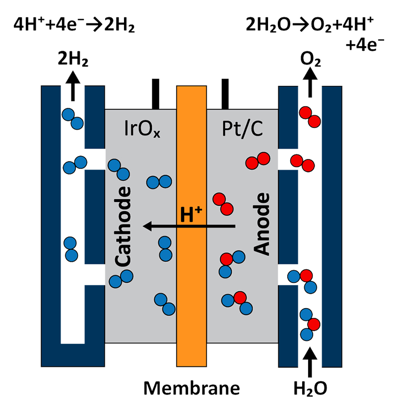
A schematic of a PEM electrolyzer cell assembly is shown in Figure 1. Essential to the overall performance of the cell is the catalyst coated membrane (CCM) which is composed of a polymer electrolyte membrane (such as Nafion or Aquivion) located at the center of the device. Each side of the CCM contains a catalyst layer that functions as the anode and cathode. Water is flown into the anode-side of the cell where it meets with iridium oxide (IrOx) to become oxidized into gaseous O2, protons (H+), and electrons (e-). Protons migrate through the CCM while electrons are conducted through the external circuit, where both meet at the cathode. A platinum and carbon-containing layer is located on the cathode-side of the CCM, where gaseous H2 is generated through the hydrogen reduction reaction.
The uniquely acidic environment within the reaction cell requires the use of noble metal catalysts [3]. State-of-the-art electrolyzer cells utilize Ir- and Pt-based anodes and cathodes, respectively. While numerous noble-metal-free cathode materials have been demonstrated, the dependence on Ir as an anode material remains the bottleneck that is preventing near-term commercialization of PEM electrolyzers [4].
Manufacturing Process Flow
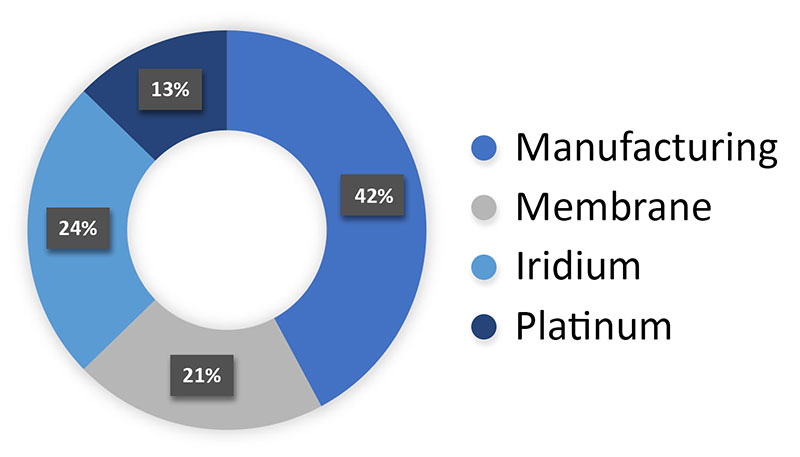
The conventional CCM fabrication process involves several multi-step manufacturing segments involving expensive and scarce materials. As shown in Figure 2, manufacturing represents a significant portion of the overall CCM fabrication cost, or 42% on average, whereas the cost of iridium accounts for 24% of the total cost.
Catalyst powder synthesis involves a wet chemistry approach that precipitates nanoparticles from solution followed by filtration and drying [5]. A CCM producer will often prepare catalyst ink by combining the raw catalyst powder with an ionomer solution and solvent, then use spray or slot-die (inkjet) coating methods to deposit the catalyst layer onto a membrane. During spraying processes, an ink containing a relatively low fraction of the catalyst component is sprayed several times to build up the coating layer-by-layer. On the other hand, the inkjet approach involves forcing the catalyst ink through a precisely machined head via injection pump to print a continuous catalyst layer onto the membrane substrate. In both cases, all non-catalyst components need to be removed from the as-deposited slurry. This is usually achieved through controlled evaporation. Kinetics of the drying process strongly influence the final catalyst distribution, porosity, and wetting characteristics which are tightly linked to the electrolyzer device performance. Non-optimized drying can result in crack formation within the CCM and significantly limit the device reliability.
Spark Ablation Technology
Spark ablation can produce a nanoparticle aerosol by applying a fast (1-10 us) high-voltage spark across two closely spaced electrodes. Being a completely dry process, it eliminates the possibility of residual surface contamination, meaning the purity of the produced catalyst particles depends only on the purity of the electrodes and carrier gas. In contrast, colloidal synthesis entails the removal of solvents, usually through calcination, which can result in residual surface contamination on the catalyst particles. Even small amounts of contamination can reduce the activity of catalyst nanoparticles. Therefore, spark ablation is a great alternative to the conventional wet chemistry approach used to produce the catalyst powder found PEM-based electrolyzer CCMs.
The VSP-G1 Nanoparticle Generator from VSParticle is a commercial instrument for generating small batches of pure and ligand-free metal nanoparticles in the size range of 1-20 nm. Process inputs include the electrode material, inert gas, and the voltage applied across the electrodes. Using the instrument is straightforward and since it operates at room temperature, setting it up takes only a few minutes. Simply by attaching the desired collection module, the particles can be collected for downstream use or directly deposited on filter papers, membranes, or substrates.
Additive Manufacturing Approach
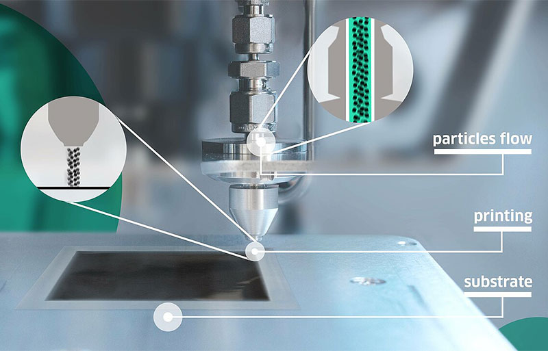
The VSP-P1 NanoPrinter builds upon this spark ablation technology by integrating an additive manufacturing platform. Using internal impaction to accelerate particles through a precision-machined nozzle, the particles in the nano aerosol stream can be locally deposited at room temperature onto the substrate (Figure 3).
This configuration enables faster development cycles for thin films and layers with high surface-area-to-volume ratio, such as Ir-coated CCMs. Compared to the conventional CCM fabrication route, the VSP-P1 is much simpler solution that enables nanoparticle generation and deposition to be implemented in a single step while avoiding the need for thermal treatments that can risk residual contamination and cracking in the catalyst layer.
Performance of CCMs fabricated with the VSP-P1 NanoPrinter
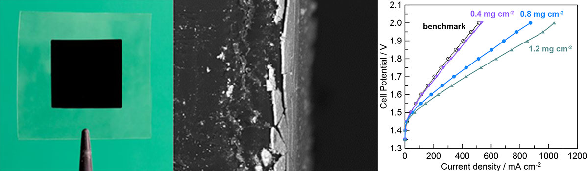
Anode-coated CCMs were fabricated by directly depositing spark-ablated Ir nanoparticles onto Nafion-115 substrates at loadings of 0.4, 0.8, and 1.2 mg/cm2 using the VSP-P1 NanoPrinter [6]. Table 1 contains the deposition parameters; printing speed was varied to modulate catalyst loading. Optical and SEM imaging confirms the presence of a continuous, dense, yet nanoporous layer (Figure 4a-b).
To evaluate the performance of the additively manufactured anode-coated CCMs, each sample was compared to a commercial benchmark anode containing IrRuOx (2 mg/cm2) deposited onto Nafion-115. All samples were mechanically attached to cathodes made of Pt-C cloth on the uncoated side of the membrane. Figure 4c shows polarization curves from each sample at 60°C where higher current density at a given cell potential indicates better performance. Not only is the anode-coated CCM containing a loading of 0.4 mg/cm2 match the commercial sample, it requires one-fifth the amount of catalyst material. At twice the loading, 0.8 mg/cm2, significantly better performance is observed while still containing less than half the amount of catalyst as the benchmark. Increasing the catalyst loading to 1.2 mg/cm2 results in more than twice the current density of the benchmark while still containing less catalyst material.
| Power | 13W |
| Carrier gas & flow rate | Ar, 2 L/min |
| Substrate vacuum | 1 mbar |
| Layer size | 2 x 2 cm2 |
| Pattern | 100 parallel lines, 20 mm in length each |
| Printing speed | Varied |
Table 1: Deposition parameters for the anode layer CCM samples [6].
Conclusion
Technologies that simplify the manufacturing process and improve material utilization efficiency of CCMs are critical for the future industrialization of green hydrogen technologies like PEM electrolyzers. The VSP-P1 NanoPrinter utilizes spark ablation and impaction printing to enable a one-step additive manufacturing platform for fabrication of nanoporous layers. This technology was used to create Ir-based anodes that maintain industrially relevant performance while reducing Ir utilization by 5x.
References:
[1] M. Wappler, D. Unguder, X. Lu, H. Ohlmeyer, H. Teschke and W. Lueke, “Building the green hydrogen market – Current state and outlook on green hydrogen demand and electrolyzer manufacturing,” International Journal of Hydrogen Energy, vol. 47, no. 79, pp. 33551-33570, 2022.
[2] S. S. Kuma and H. LIm, “An overview of water electrolysis technologies for green hydrogen production,” Energy Reports, vol. 8, pp. 13793-13813, 2022.
[3] F. M. Sapountzi, J. M. Gracia, C. (.-J. Weststrate, H. O. Fredriksson and J. (. Niemantsverdriet, “Electrocatalysts for the generation of hydrogen, oxygen and synthesis gas,” Progress in Energy and Combustion Science, vol. 58, pp. 1-35, 2017.
[4] IRENA, “Green Hydrogen Cost Reduction: Scaling up Electrolysers to Meet the 1.5° Climate Goal,” International Renewable Energy Agency, Abu Dhabi, 2020.
[5] D. G. Norton, L. N. Lewis, E. W. Shanklin, F. J. Klug, V. S. Venkataramani, R. J. Lyons, D. Hancu, B. H. Winkler and H. Keshavan, “Process for preparing catalyst powder”. United States Patent US20110166015A1, July 2011.
[6] F. M. Sapountzi, M. Lavorenti, W. Vrijburg, S. Dimitriadou, B. Tyburska-Pueschel, P. Thüne, H. Niemantsverdriet, T. V. Pfeiffer and M. N. Tsampas, “Spark Ablation for the Fabrication of PEM Water Electrolysis Catalyst-Coated Membranes,” Catalysts, vol. 12, no. 11, p. 1343, 2022.