Table of Contents
What are Nanoparticles?
Nanoparticles are integral components in a wide variety of applications, including medicine, semiconductors, catalysis, and energy. They are defined as particles with a size between 1-1000 nm. At smaller size scales, particles can behave differently than their bulk counterparts. For example, as particles become smaller, their surface area increases greatly. This allows for properties such as increased electrical and thermal conductivity, lowered melting points, stronger magnetism or unique optical properties to arise [1]. For the development of advanced materials, the ability to consistently utilize materials at this size provides a wealth of opportunities in fields such as clean energy, catalysis, and sensors to name a few.
What are some applications of nanoparticles?
Nanoparticles currently exist in a wide variety of consumer products. They can be applied as fillers or coatings for UV protection, which are important in windows, lenses, and sunscreens [2]. The known antimicrobial properties of materials such as silver and copper can be incorporated as nanoparticles to keep packaged foods fresh or to reduce odor in socks. In medicine, gold nanoparticles have been widely studied as a potential agent for targeted drug delivery and cancer detection [3]. For reaction catalysis, nanoparticle effectiveness compared to bulk materials is primarily driven by the huge increase in surface area when particle size decreases. This leads to much more efficient application of the catalyst material [4]. In the field of plasmonics, nanoparticles are routinely exploited for their unique optical properties called surface plasmons that can be used for enhanced detection in Raman spectroscopy commonly called Surface-Enhanced Raman Spectroscopy (SERS).
How are nanoparticles made?
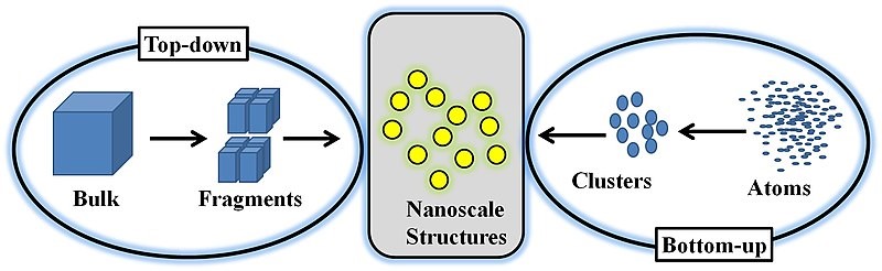
Nanoparticles are typically synthesized from a top-down or bottom-up approach. A bottom-up approach relies on nucleating atomic-sized materials into the eventual nanoparticles. While the exact synthesis method depends on the material being generated, some common methods include the Turkevich method (citrate reduction), gas phase synthesis, block copolymer synthesis, and more recently, microbial synthesis [1, 5, 6]. Top-down methods, where a bulk material is physically broken down to make smaller molecules, include milling, laser ablation, and spark ablation.
Bottom-up synthesis methods are often termed “wet” methods since they involve batches of solvents and other chemicals. Additionally, the particles often must be stabilized or capped in solution to ensure that they do not continue to grow past the nanoscale range. The particles then usually need to be moved or transferred from their solutions for their application or characterization. This can be accomplished by drop-casting the solution onto the substrate of interest. However, in some applications, such as catalysis, it may also be necessary to remove the stabilizers from the surface of the nanoparticles after they have been immobilized on the final support of interest. The removal process can prove difficult or even impossible, leading these particles to be unusable for their intended purpose (see [7] for example).
Colloidal nanoparticle synthesis
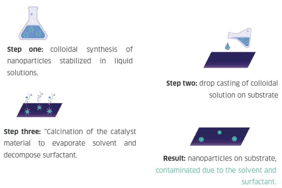
Nanoparticles are traditionally synthesized using wet chemistry methods, which involve first generating the particles in a solution, drop casting the wet particles onto a substrate, and removing the solvent, surfactants, and other materials from the particles. This wet synthesis method requires a significant amount of time and chemicals, and the resultant material may be contaminated with residues from the solution.
Spark ablation nanoparticle synthesis
One promising alternative to wet synthesis is spark ablation. Spark ablation utilizes two electrodes of the metal(s) of choice and applies a fast (1-10 μs) high-voltage spark onto the two electrodes. The spark produces an aerosol of pure particles from the two ablated metals, which are then transferred to a downstream substrate. The resulting nanoparticles are made of pure metal, and no post-processing steps such as drying or surfactant decomposition is required. Thus spark ablation is a safer, greener, and more economical way of producing high-quality research or production-grade nanoparticles.
How spark ablation works
Spark Ablation requires a spark discharge generator, which has the following basic parts:
- Electrodes of the metal of choice
- Carrier gas inlet
- Substrate for particle collection
- Voltage source
- Reactive gas inlet (optional)
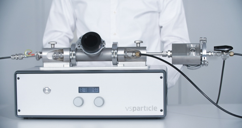
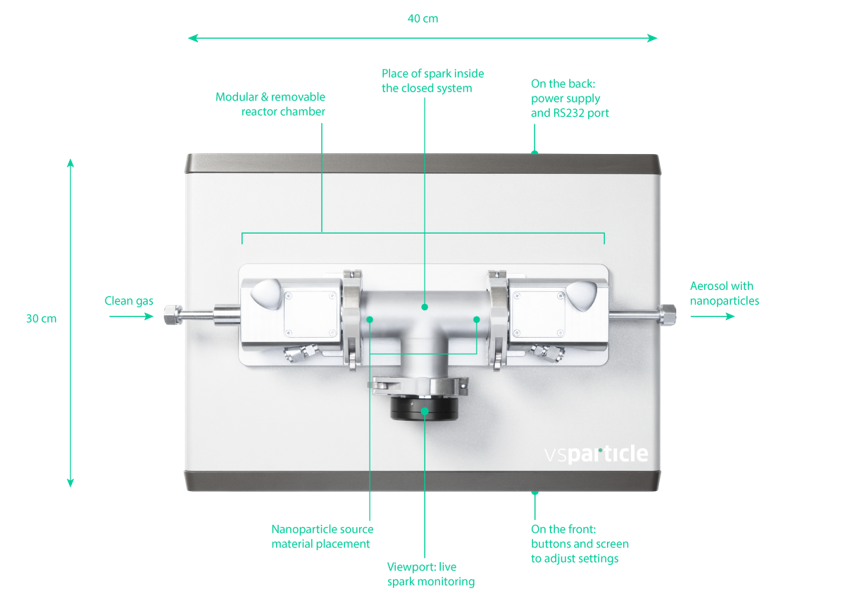
The VSParticle VSP-G1 system is one such commercial system that contains all the above parts to allow for one-touch spark ablation experiments.
The electrical components of the spark discharge generator include a voltage source, resistor, capacitor, and inductor. The general circuit diagram for a spark discharge generator is shown in Figure 5. The frequency (f) of sparks is modulated according to the equation:
f |
= |
I |
||
2CŪ |
||||
Equation of sparks frequency
Where I is the current, C is capacitance, and Ū is the mean voltage. [8]
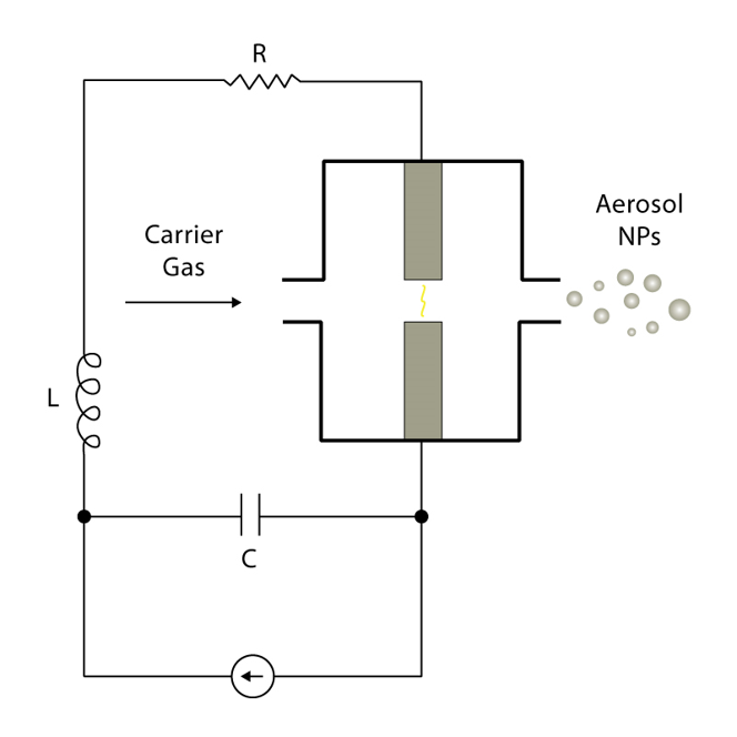
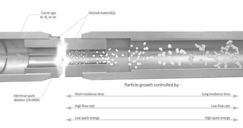
As voltage is applied, the capacitor eventually discharges, causing a high temperature spark (>20,000 K) that ablates the metal electrode. The carrier gas then transfers the particles to a substrate of the researcher’s choice. Some potential substrate options include TEM grids, electrodes, and metal meshes.
Control of key particle parameters, such as size, distribution, concentration, and coverage, is dictated by the gas flow rate, voltage, current, and time. The gas flow rate is the primary controller for most of the key particle characteristics. It affects how large and concentrated particles become before they are carried downstream, where faster rates will reduce the ability of the particles to aggregate, hence resulting in smaller particles with a smaller size distribution. Higher flow rates also increase the concentration and coverage on the downstream substrate.
As voltage is applied, the capacitor eventually discharges, causing a high temperature spark (>20,000 K) that ablates the metal electrode. The carrier gas then transfers the particles to a substrate of the researcher’s choice. Some potential substrate options include TEM grids, electrodes, and metal meshes.
Voltage and current both affect particle size similarly in that an increase in either parameter generates larger particles. Higher values tend to generate more frequent sparks, which ablates material from the electrode more often and generates larger and more numerous particles. These parameters also increase the particle distribution size. Finally, the time that the system is operated only affects how much coverage is achieved on the downstream substrate. Table 1 summarizes how each of these parameters affect the properties of the particles generated and Figure 6 also provides a graphical illustration on these correlations.
| An increase in this parameter | Affects the nanoparticles in this way | |||
| Particle Size | Side Distribution | Particle Concentration | Sample Coverage | |
| Gas Flow Rate | ↓ | ↓ | ↑ | ↑ |
| Voltage | ↑ | ↑ | ↑ | No effect |
| Current | ↑ | ↑ | ↑ | No effect |
| Time | No effect | No effect | No effect | ↑ |
Table 1 – Nanoparticle parameter dependency on spark discharge generator inputs
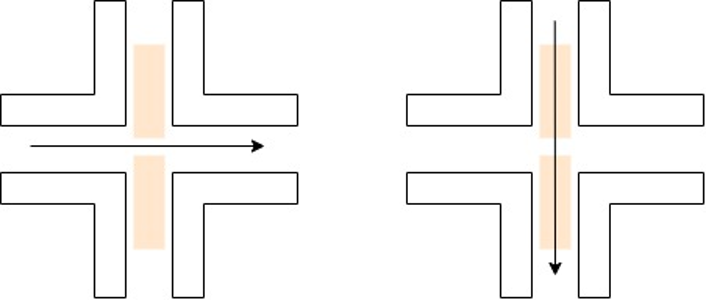
The gas flow has two primary configurations – cross flow and flow through. The flow through configuration requires hollow electrodes to allow for gas to go through the electrodes and to the eventual substrate. A cross flow gas configuration generally results in lower residence times and smaller particles. The flow through configuration can allow for specific hybrid nanoparticle configurations, which will be discussed later.
Material range and combinations
Particles beyond single element materials can also be generated by using different electrodes and gas flow configurations. For example, by ablating a gold and silver electrode, alloyed gold-silver nanoparticles can be generated. Two SA setups can also be set up in series or parallel to provide different types of agglomerated or decorated particles.
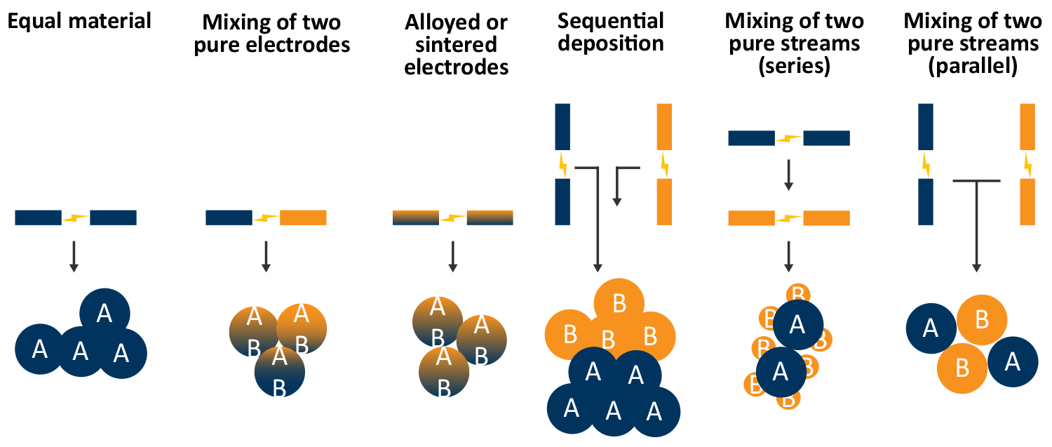
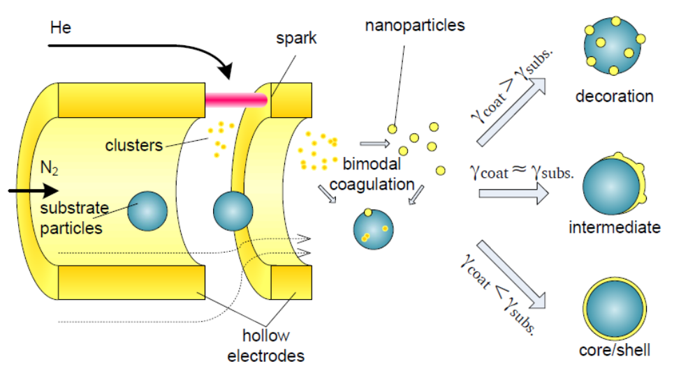
A flow through gas configuration can be beneficial for series deposition of materials, for example gold particles coated by a copper particles. Other more exotic configurations, such as core-shell nanoparticles, are also possible in this configuration. The type of multi-element nanoparticle is primarily dictated by the difference in surface energy between the initial nanoparticle and the secondary nanoparticle [9].
Overall, spark ablation offers many benefits in generating nanoparticles, including high reproducibility, fast operation, and simple setup. Hybrid nanoparticles can be generated just by using two different electrode materials, and particle parameters can be optimized by changing the gas flow rate, voltage, current, and time. Additionally, removing the need to use chemicals and solvents to generate the particles reduces the environmental impact of the process.
References
[1] R. Nagarajan, “Nanoparticles: Building Blocks for Nanotechnology,” in Nanoparticles: Synthesis, Stabilization, Passivation, and Functionalization, American Chemical Society, 2008, pp. 2-14.
[2] W. J. Stark, P. R. Stoessel, W. Wohlleben and A. Hafner, “Industrial applications of nanoparticles,” Chemical Society Reviews, vol. 44, no. 16, pp. 5793-5805, 2015.
[3] M. Rai, A. P. Ingle, S. Birla, A. Yadav and C. Alves Dos Santos, “Strategic role of selected noble metal nanoparticles in medicine,” Critical Reviews in Microbiology, vol. 42, no. 5, pp. 696-719, 2016.
[4] B. F. G. Johnson, “Nanoparticles in Catalysis,” ChemInform, vol. 35, no. 12, pp. 147-159, 2004.
[5] J. Turkevich, P. C. Stevenson and J. Hillier, “A study of the nucleation and growth processes in the synthesis of colloidal gold,” Discussions of The Faraday Society, vol. 11, no. , pp. 55-75, 1951.